
Method for improving surface quality of inner and outer rings and edge parts of oriented silicon steel and annular furnace

A surface quality, oriented silicon steel technology, applied in furnaces, furnace types, heat treatment furnaces, etc., can solve the problems of the influence of the lower end panel type, unfavorable steel coil support, and too many deflectors

Active Publication Date: 2022-02-25
武汉钢铁有限公司
View PDF6 Cites 2 Cited by
  • Summary
  • Abstract
  • Description
  • Claims
  • Application Information

AI Technical Summary

Problems solved by technology

The device can improve the flow field and temperature field in the heat treatment process of silicon steel coils, thereby improving the heat treatment quality of steel coils, and solving the problem of gas flow and exhaust at the lower end surface of steel coils. , the force point on the lower end surface of the steel coil is reduced, which is not conducive to the support of the steel coil, and it will also cause difficulty in moving the steel coil during thermal expansion and contraction, and the shape of the lower end panel will be affected

Method used


Image

  • Method for improving surface quality of inner and outer rings and edge parts of oriented silicon steel and annular furnace
  • Method for improving surface quality of inner and outer rings and edge parts of oriented silicon steel and annular furnace
  • Method for improving surface quality of inner and outer rings and edge parts of oriented silicon steel and annular furnace

Examples


Embodiment 1

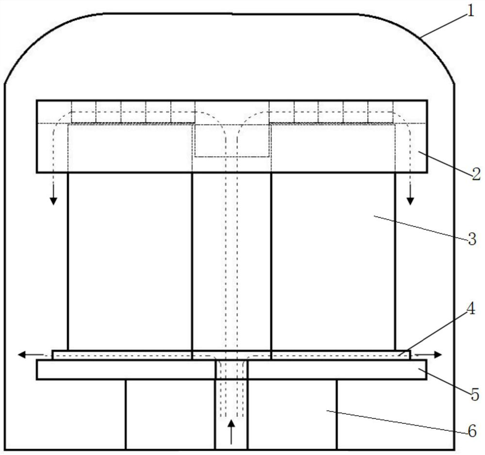
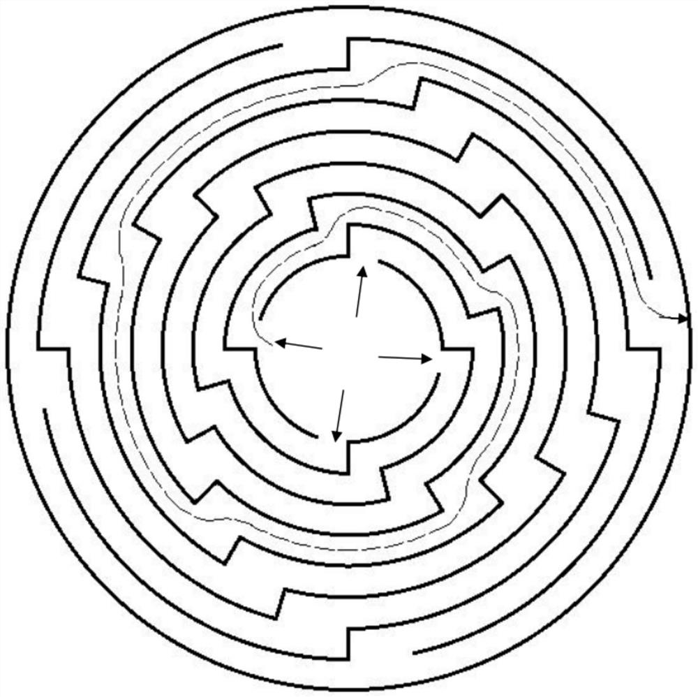
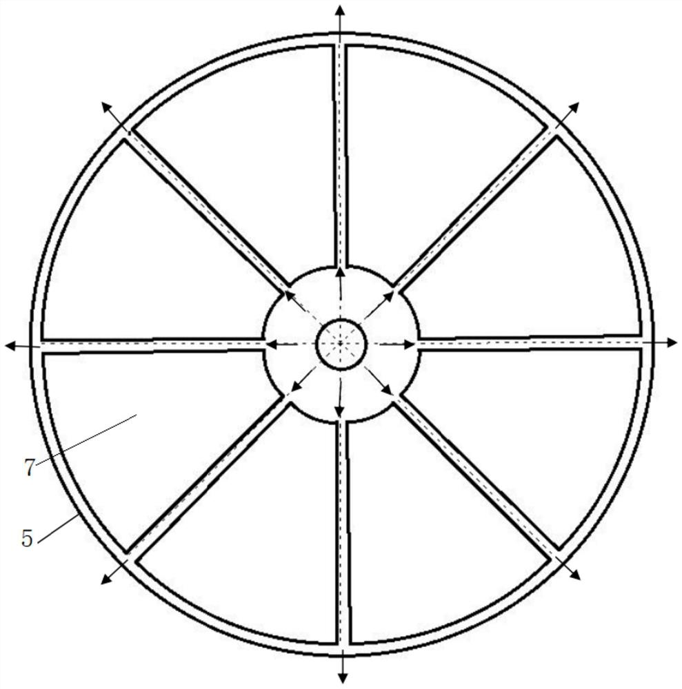
[0035] In one cold rolling process, the amount of misalignment is 1cm, and the misalignment is performed every 5cm until the curling is completed. The MgO coating amount of the head 2000m and tail 1000m is 1g / m less than that of the middle 3 ~2g / m 3 ; In the high-temperature annealing process, adopt 8 fan-shaped blocks 7, the height of the fan-shaped blocks 7 is 3cm, there is a gap of 50mm between the adjacent fan-shaped blocks 7, the width of the diversion groove is 8cm, the height is 10cm, and the middle of the bottom surface of the cover plate 2 passes through Four diversion grooves are evenly distributed around the center, and the inner ring of the bottom surface of the cover plate 2 is 10 cm higher than the diversion groove, and the outer ring is 20 cm higher than the diversion groove.

Embodiment 2

[0037] In one cold rolling process, the amount of misalignment is 0.5cm, and misalignment is performed every 2cm until the curling is completed. The amount of MgO coating at the head 3000m and tail 2000m is 1g / m less than that at the middle 3 ~2g / m 3 ; In the high-temperature annealing process, adopt 4 fan-shaped blocks 7, the height of the fan-shaped blocks 7 is 3cm, there is a gap of 100mm between the adjacent fan-shaped blocks 7, the width of the diversion groove is 12cm, the height is 15cm, and the middle of the cover plate 2 bottom surface passes There are two diversion grooves evenly distributed around the center, the inner ring of the bottom surface of the cover plate 2 is 10cm higher than the diversion groove, and the outer ring is 30cm higher than the diversion groove.

Embodiment 3

[0039] In one cold rolling process, the amount of misalignment is 0.8cm, and the misalignment is performed every 4cm until the curling is completed. The MgO coating amount of the head 2000m and tail 1000m is 1g / m less than that of the middle 3 ~2g / m 3 ; In the high-temperature annealing process, adopt 6 fan-shaped blocks 7, the height of the fan-shaped blocks 7 is 4cm, there is a gap of 50mm between the adjacent fan-shaped blocks 7, the width of the diversion groove is 10cm, the height is 10cm, and the middle of the bottom surface of the cover plate 2 passes There are three diversion grooves evenly distributed around the center, the inner ring of the bottom surface of the cover plate 2 is slightly higher than the diversion grooves, and the outer ring is 20cm higher than the diversion grooves.

[0040] For comparative examples 1, 2, 3, and 4, the conventional CA coiling method and the conventional annular furnace charging method were adopted, and the implementation effects are ...


PUM

PropertyMeasurementUnit
heightaaaaaaaaaa
heightaaaaaaaaaa

Abstract

The invention discloses a method for improving the surface quality of inner and outer rings and edge parts of oriented silicon steel and an annular furnace. In a primary cold rolling process, misalignment crimping is adopted, crimping tension is controlled according to gradual change tension, the crimping tension at the head and the tail is large, and the crimping tension at the middle part is small; the coating amount of MgO and the curling tension change synchronously, the coating amount of the head and the tail is small, and the coating amount of the middle part is large; in the high-temperature annealing process, a cushion layer formed by evenly distributing a plurality of fan-shaped blocks around the center is additionally arranged on a bottom plate of the annular furnace, gaps exist between the adjacent fan-shaped blocks, and the upper end of a steel coil in an inner cover of the annular furnace is covered with a ventilated cover plate. An inner ring gap of the bottom surface of the cover plate extends into a steel coil hole, an outer ring gap sleeves a steel coil, the middle of the cover plate is supported on the end surface of the steel coil through diversion trenches uniformly distributed around the center, the diversion trenches are spiral, inlets of the diversion trenches are communicated with openings in the inner ring of the cover plate in a one-to-one correspondence manner, and outlets of the diversion trenches extend to the inner side of the outer ring of the bottom surface of the cover plate. The method can obviously reduce surface defects, obviously improve surface quality and magnetism, and is easy to operate.

Description

technical field [0001] The invention belongs to the field of oriented silicon steel, and in particular relates to a method for improving the surface quality of the inner and outer rings and edges of oriented silicon steel and an annular furnace. Background technique [0002] Oriented silicon steel is an excellent soft magnetic material. Its magnetization has strong directionality, high magnetic induction in the required direction, and low iron loss. It is the most critical and important in the manufacture of electromagnetic directional conversion products such as transformers and transformers. Iron core material, but its production process is complicated, the control precision is high, and the production is difficult. [0003] The production process of grain-oriented silicon steel includes: steelmaking-hot rolling-pickling normalization-primary cold rolling-decarburization annealing-high temperature annealing-hot stretching and tempering. Among them, 2.8% to 3.5% silicon in...

Claims


Application Information

Patent Timeline
Patent Type & Authority Applications(China)
IPC IPC(8): C21D8/12C21D1/26C21D9/673
CPCC21D8/1233C21D8/1238C21D8/1244C21D8/1283C21D1/26C21D9/673Y02P10/20
Inventor 骆新根郭小龙高洋程祥威刘敏申明辉丁哲
Owner 武汉钢铁有限公司
Learn More