
Engine cylinder closing valve control device and method

A control device and engine block technology, applied in the direction of engine control, engine components, machines/engines, etc., can solve the problems of difficult to meet engine cylinder closure, fast wear speed, low reliability, etc., to improve reliability and meet high Frequency response and reliability, the effect of simplifying the control process

Active Publication Date: 2022-02-25
LONGKOU ZHONGYU THERMAL MANAGEMENT SYST SCIAND TECH
View PDF7 Cites 2 Cited by
  • Summary
  • Abstract
  • Description
  • Claims
  • Application Information

AI Technical Summary

Problems solved by technology

Existing engine cylinder deactivation technologies are mostly based on the rocker arm structure, such as figure 1 The traditional engine rocker arm type valve transmission mechanism shown, by blocking the connection between the valve rocker arm and the valve, makes the valve in the normally closed state, and realizes the oil and gas stop when the cylinder is closed; but due to the high-speed operation of the engine, The above-mentioned mechanical blocking structure responds at high frequency under the high-frequency action of the throttle rocker arm, which leads to fast wear and low reliability of the mechanical blocking structure, and it is difficult to meet the needs of the engine cylinder deactivation

Method used


Image

  • Engine cylinder closing valve control device and method
  • Engine cylinder closing valve control device and method
  • Engine cylinder closing valve control device and method

Examples


Embodiment 1

[0035] In a typical embodiment of the present invention, such as Figure 2-Figure 5 As shown, an engine cylinder deactivation valve control device is given.

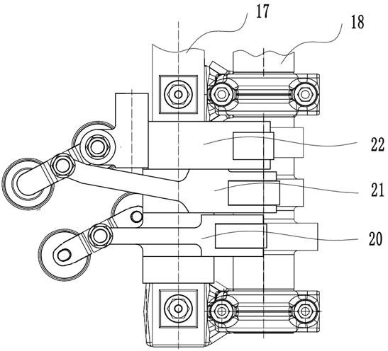
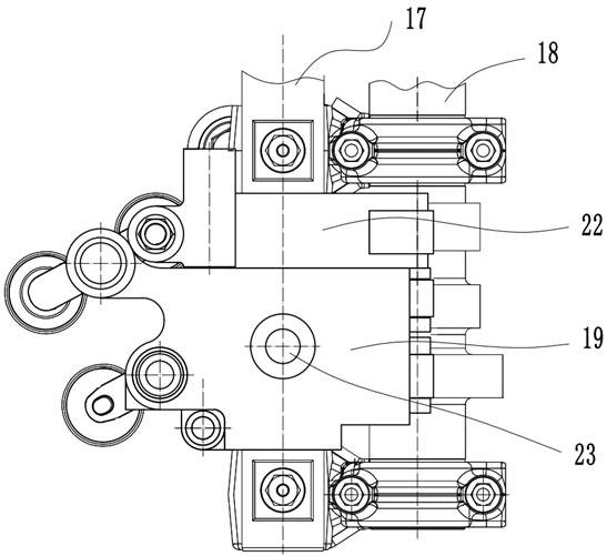
[0036] Such as figure 1 Shown is a traditional engine rocker valve control structure, the intake rocker 20, exhaust rocker 21, brake rocker 22 are connected in series through the rocker shaft 17, the rocker is driven by the camshaft 18, and then the rocker is driven The valve bridge, and then the valve bridge drives the valves to work. Such as figure 2 As shown, the engine cylinder deactivation control device provided in this embodiment is used as the cylinder deactivation control mechanism 19 to replace the original intake rocker arm 20, exhaust rocker arm 21 and brake rocker arm 22, and is also connected in series on the rocker arm shaft 17. Driven by the camshaft 18, but integrally fixed on the cylinder head, it cannot swing around the rocker shaft 17 driven by the camshaft 18.

[0037] figure 2 , image 3 Sho...

Embodiment 2

[0059] In another typical embodiment of the present invention, such as Figure 2-Figure 5 As shown, a method for controlling the cylinder-closing valve of the engine is given, using the engine cylinder-closing valve control device as in Embodiment 1.

[0060] During normal engine block operation:

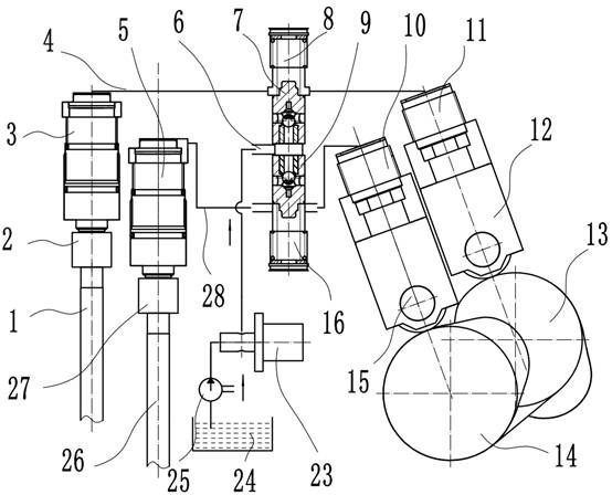
[0061] The control valve 23 obtains the medium supplied by the hydraulic pump 25 and inputs it to the control port of the spool valve, and the spool of the spool valve moves;

[0062] The spool valve core opens the middle passage, so that the valve oil circuit remains connected, and the external hydraulic tappet periodically transmits the driving force to the external hydraulic piston under the action of the camshaft 18, so that the hydraulic piston drives the valve to periodically move;

[0063] When the engine block is closed:

[0064] The control valve 23 obtains the medium supplied by the hydraulic pump 25 and inputs it to the control port of the spool valve, and the spool of ...


PUM


Abstract

The invention provides an engine cylinder closing valve control device and method, and relates to the technical field of engines. The engine cylinder closing valve control device comprises a valve oil way and a control oil way; the control oil way comprises a sliding valve, a control valve and a hydraulic pump; the hydraulic pump is connected into a control port of the sliding valve through the control valve; the sliding valve is provided with a middle channel and a valve element; the valve oil way is connected with the middle channel in series; the control valve adjusts the position of the valve element through the control port so that the valve element can block or open the middle channel. For solving the problem that the reliability is low when a mechanical blocking structure is adopted during cylinder closing of an existing engine, the sliding valve is arranged on a driving valve oil way, the driving valve oil way is blocked or opened through the sliding valve, and the valve can be closed to achieve cylinder closing during blocking; and during opening, the driving valve oil way can operate normally, normal driving of a valve is kept, and the working requirements of an engine in different states are met.

Description

technical field [0001] The invention relates to the technical field of engines, in particular to an engine cylinder deactivation valve control device and method. Background technique [0002] Engine cylinder deactivation technology can reduce pollution during operation. When the vehicle is running smoothly, the engine will automatically close one of the cylinders, two cylinders or more cylinders to drive the vehicle forward, so that some cylinders work and some cylinders deactivate, reducing energy consumption and improve its utilization. [0003] At present, there are mainly two methods in the practical application of cylinder deactivation technology. One is to stop fuel and stop gas. During the operation of the engine, some cylinders stop fuel injection, but the intake valve still operates normally, but the fuel saving effect is not ideal; One is to stop fuel and gas. During the engine movement, when some cylinders stop fuel injection, the corresponding valves also stop o...

Claims


Application Information

Patent Timeline
Patent Type & Authority Applications(China)
IPC IPC(8): F02D13/06F02D13/02F01L9/10
CPCF02D13/06F02D13/02F01L9/10
Inventor 王兆宇李小霞郑建松李光明
Owner LONGKOU ZHONGYU THERMAL MANAGEMENT SYST SCIAND TECH
Learn More