Display module, display device and electrostatic isolation method

A display module and static electricity technology, applied in the direction of static electricity, electrical components, static indicators, etc., can solve problems affecting user use, abnormal LCD panel screen, and changes in the internal control logic of the drive chip, so as to improve antistatic ability and improve The effect of user experience

Active Publication Date: 2022-02-25
CHANGSHA HKC OPTOELECTRONICS CO LTD +1
View PDF20 Cites 0 Cited by
  • Summary
  • Abstract
  • Description
  • Claims
  • Application Information

AI Technical Summary

Problems solved by technology

[0002] At present, when driving the display panel, the driver chip is often used to control the display of the liquid crystal panel. However, due to the existence of static electricity, a part of the static electricity will pass through the driver chip and the driver circuit board to form a loop, resulting in changes in the internal control logic of the driver chip. Therefore, it will cause the screen of the LCD panel to be abnormal and affect the user's use.

Method used


Image

  • Display module, display device and electrostatic isolation method
  • Display module, display device and electrostatic isolation method
  • Display module, display device and electrostatic isolation method

Examples


Embodiment 1

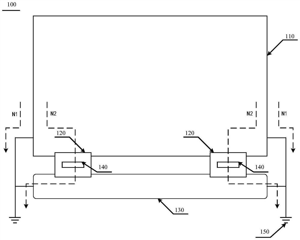
[0046] like figure 1 as shown, figure 1 A schematic structural diagram of a display module 100 corresponding to Embodiment 1 of the present application is schematically shown.

[0047] Embodiment 1 of the present application provides a display module 100, including a display panel 110, a driver chip 120, and a driver circuit board 130. The driver chip 120 is connected to the driver circuit board 130 and the display panel 110, respectively. 110 provides a drive signal. Wherein, the display module 100 further includes an electrostatic isolation unit 140 disposed between the ground terminal 121 of the driving chip and the ground terminal 131 of the driving circuit board.

[0048] The electrostatic isolation unit 140 of the present application may be integrated in the driving chip 120 , or may be separately provided and connected to the driving chip 120 . Wherein, the ground terminal 121 of the driving chip and the ground terminal 131 of the driving circuit board are both system ...

Embodiment 2

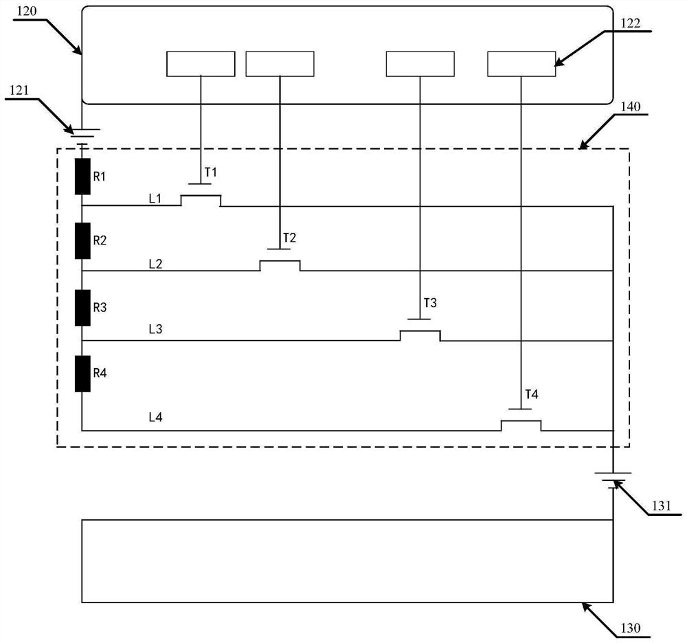
[0063] like image 3 as shown, image 3 A circuit diagram of an electrostatic isolation unit corresponding to Embodiment 2 of the present application is schematically shown.

[0064] Embodiment 2 and Embodiment 1 of the present application both include a plurality of electrostatic isolation branches, and each electrostatic isolation branch includes an isolation resistor and a switching transistor. Since this part is the same as Embodiment 1, it is not repeated here repeat.

[0065] The difference between the second embodiment and the first embodiment lies in that the composition of each branch and the connection relationship of the isolation resistors on each branch are different.

[0066] In the electrostatic isolation unit 140 of Embodiment 2 of the present application, in any two adjacent electrostatic isolation branches of the present application, the first end of the isolation resistor of the latter is connected to the second end of the isolation resistor of the former,...

Embodiment 4

[0092] like Image 6 as shown, Image 6 A circuit diagram of an electrostatic isolation unit corresponding to Embodiment 4 of the present application is schematically shown.

[0093] In the electrostatic isolation unit 140 of Embodiment 4 of the present application, the electrostatic isolation unit 140 of the present application further includes a short-circuit branch L', and the short-circuit branch L' includes at least one switching transistor, and the first end of the switching transistor is connected to the drive The ground terminal 121 of the chip is connected, and the second terminal is connected with the ground terminal 131 of the driving circuit board, and the switching transistor is used to respond to the control signal of the driving chip 120, so that the ground terminal 131 of the driving circuit board is shorted with the ground terminal 121 of the driving chip .

[0094] The short-circuit branch L' is not connected to the corresponding branch of the isolation res...


PUM


Abstract

The invention belongs to the technical field of display panels, and particularly relates to a display module, a display device and an electrostatic isolation method. The display module comprises a display panel, a driving chip and a driving circuit board, wherein the driving chip is connected with the driving circuit board and the display panel and is used for providing a driving signal for the display panel. The display module further comprises an electrostatic isolation unit which is arranged between a grounding end of the driving chip and a grounding end of the driving circuit board. According to the invention, the electrostatic isolation unit is arranged between the grounding end of the driving chip and the grounding end of the driving circuit board, and most static electricity between the grounding end of the driving chip and the grounding end of the driving circuit board is isolated through the electrostatic isolation unit, so that the problem of an abnormal picture of the panel caused by a loop formed by the static electricity after passing through the driving chip and the driving circuit board is solved, antistatic capabilities of the display module can be effectively improved, and the use experience of a user is improved.

Description

technical field [0001] The application belongs to the technical field of display panels, and in particular relates to a display module, a display device and an electrostatic isolation method. Background technique [0002] At present, when driving the display panel, the driver chip is often used to control the display of the liquid crystal panel. However, due to the existence of static electricity, a part of the static electricity will pass through the driver chip and the driver circuit board to form a loop, resulting in changes in the internal control logic of the driver chip. Therefore, abnormality of the picture of the liquid crystal panel may be caused, which affects the use of the user. Contents of the invention [0003] The purpose of the present application is to provide a display module, a display device and an electrostatic isolation method, which can at least to some extent overcome the technical problem in the related art that static electricity causes an abnorma...

Claims


Application Information

Patent Timeline
IPC IPC(8): G09G3/36G09G3/3208H05F3/02
CPCG09G3/36G09G3/3208H05F3/02
Inventor 蒋勇杰袁海江
Owner CHANGSHA HKC OPTOELECTRONICS CO LTD
Why Eureka
Try Eureka