Bias radio frequency and direct current power supply conveying device for thin film growth equipment

A technology of thin film growth and DC power supply, applied in the direction of joining/disconnecting connecting components, coupling devices, components of connecting devices, etc., can solve the problems of uncontrollable joint fit, waste of time, copper strip corrosion, etc. , to achieve the effect of improving work efficiency, good heat dissipation performance and reducing corrosion

Pending Publication Date: 2022-02-25
盛吉盛(宁波)半导体科技有限公司
View PDF0 Cites 0 Cited by
  • Summary
  • Abstract
  • Description
  • Claims
  • Application Information

AI Technical Summary

Problems solved by technology

[0005] The purpose of the present invention is to provide a transmission device for bias radio frequency and DC power supply for thin film growth equipment, which solves the problem that whether it is the direct current used to absorb silicon wafers or the matching radio frequency, the bias matcher is transmitted to the device through this device. On the electrostatic chuck, since the device is screwed to connect the joint and then inserted into the joint of the bias matcher, the long-term heat generation cannot control the fit of the joint, and electric corrosion is prone to occur, and the copper strip will be corroded together in severe cases. It is troublesome to replace. You need to open the chamber after running the cleaning procedure, and then take out and replace the electrostatic chuck after it is completely disassembled. This process takes about two to three hours, which is a waste of time.

Method used


Image

  • Bias radio frequency and direct current power supply conveying device for thin film growth equipment
  • Bias radio frequency and direct current power supply conveying device for thin film growth equipment

Examples


Embodiment Construction

[0018] The following will clearly and completely describe the technical solutions in the embodiments of the present invention with reference to the accompanying drawings in the embodiments of the present invention. Obviously, the described embodiments are only some, not all, embodiments of the present invention. Based on the embodiments of the present invention, all other embodiments obtained by persons of ordinary skill in the art without making creative efforts belong to the protection scope of the present invention.

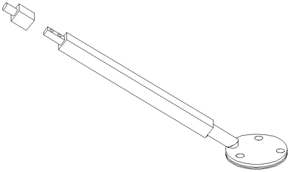
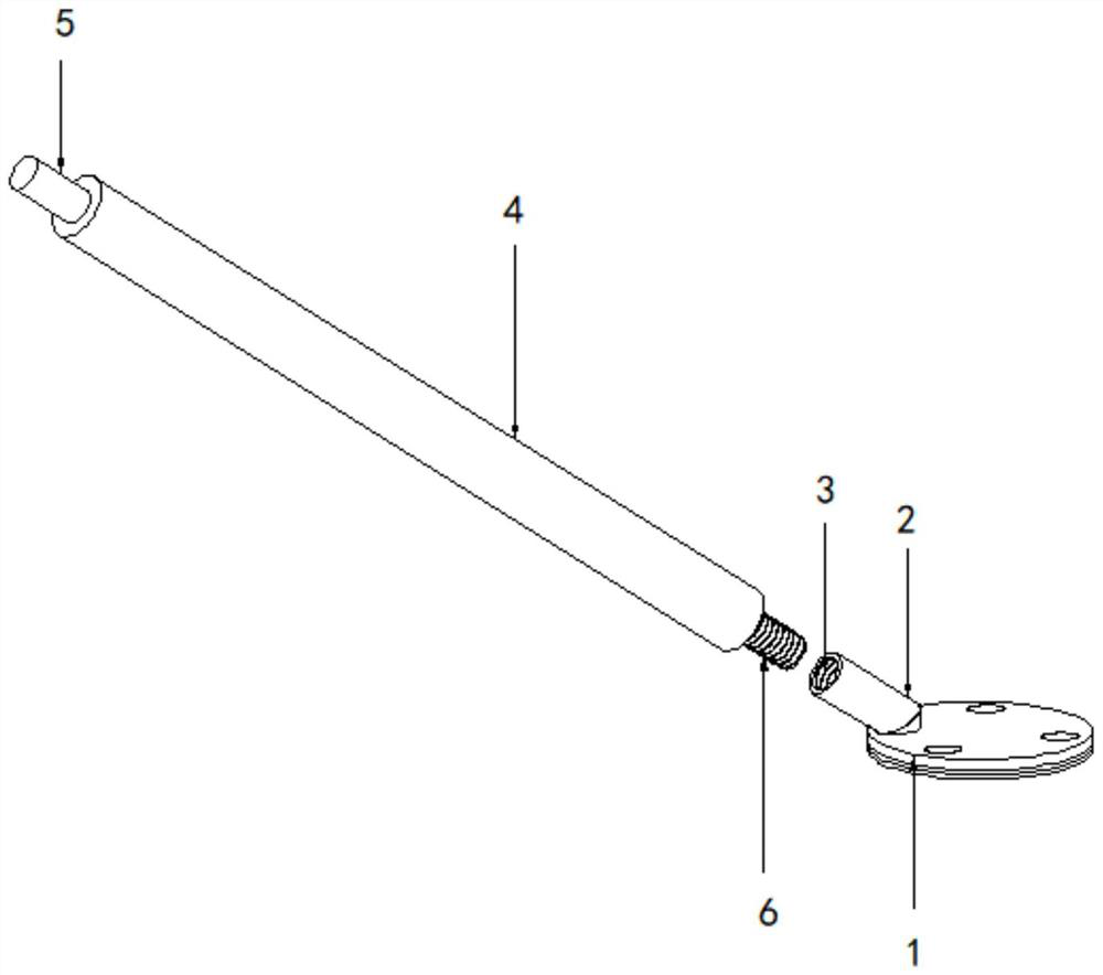
[0019] see figure 2 , the present invention provides a technical solution: a transmission device for bias radio frequency and DC power supply of thin film growth equipment, including: electrostatic chuck 1, the upper part of the electrostatic chuck 1 is provided with a connection head 2 and the electrostatic chuck 1 There is a fixed connection between them, the inside of the connector 2 is provided with an internal threaded hole 3, the upper part of the conne...


PUM


Abstract

The invention discloses a bias radio frequency and direct current power supply conveying device for thin film growth equipment, which comprises an electrostatic chuck, the upper part of the electrostatic chuck is provided with a connector which is fixedly connected with the electrostatic chuck, and the connector is internally provided with an internal threaded hole; a copper rod is arranged on the upper portion of the connector, a connecting plug is arranged on the top of the copper rod, and the connecting plug is connected with the offset matcher. A copper bar part is replaced by the copper rod, the cross section of the copper rod is round, the area is larger, larger load current can be met, meanwhile, the heat dissipation performance is better, and the probability of electrocorrosion is reduced; the connector and the copper rod are combined by the bias matcher end, so that a corrosion part is reduced; the end of the electrostatic chuck is made into a separated structure, so that the connector can still be fixed on the back of the electrostatic chuck, the other end of the connector can be screwed in through threads, and if the other end of the copper rod is corroded, the connector can be directly screwed off for replacement without opening the cavity and decomposing the electrostatic chuck.

Description

technical field [0001] The invention relates to the technical field of transmission of bias radio frequency and direct current power, more specifically a transmission device for bias radio frequency and direct current power used in thin film growth equipment. Background technique [0002] High-density plasma chemical vapor deposition often uses electrostatic chucks to give silicon wafers adsorption and cooling. At the same time, during the film growth reaction process, the deviation matcher will give the electrostatic chucks a bias voltage through capacitive coupling, so that it is suitable for the plasma. The body has a vertical downward driving force. [0003] The bias RF / DC power transmission device connected under the electrostatic chuck, when connected to the bias matcher, because the long-term current transmission joint is prone to electrochemical corrosion, if the phenomenon is serious, it will corrode the copper strip and cause the electrostatic chuck Unable to work...

Claims


Application Information

Patent Timeline
Patent Type & Authority Applications(China)
IPC IPC(8): H01R13/622H01R4/60
CPCH01R13/622H01R4/60
Inventor 蔡宇航金補哲叶新浩厉冰峰
Owner 盛吉盛(宁波)半导体科技有限公司
Why Eureka
Try Eureka