Capacitor energy storage type pulse step current generating power supply

A capacitor energy storage type, pulse ladder technology, applied in electrical components, conversion equipment without intermediate conversion to AC, DC power input converted to DC power output, etc., can solve the problem of unable to generate stepped pulse current.

Pending Publication Date: 2022-02-25
SOUTHWESTERN INST OF PHYSICS
View PDF7 Cites 0 Cited by
  • Summary
  • Abstract
  • Description
  • Claims
  • Application Information

AI Technical Summary

Problems solved by technology

A spherical tokamak refers to a tokamak device with a ring diameter ratio of less than 1.5, usually using a cheap and flexible capacitor bank to store energy. Uncontrolled discharge, can only generate a current flat top, can not generate a ladder-like pulse current

Method used


Image

  • Capacitor energy storage type pulse step current generating power supply
  • Capacitor energy storage type pulse step current generating power supply
  • Capacitor energy storage type pulse step current generating power supply

Examples


Embodiment 1

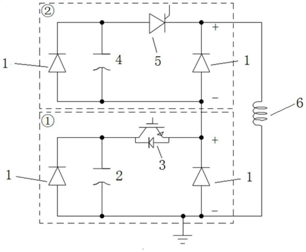
[0029] like figure 1 As shown, a capacitive energy storage type pulse ladder current generating power supply provided by the present invention is composed of a low-voltage module and a high-voltage module:

[0030] The low-voltage module includes two diodes 1, a large-capacity low-voltage capacitor 2, and an insulated gate bipolar transistor IGBT3. The large-capacity low-voltage capacitor 2 is connected in reverse parallel with a diode 1, and the parallel circuit is connected in series with the insulated gate bipolar transistor IGBT3. The collector of the gate bipolar transistor IGBT3, the emitter of the insulated gate bipolar transistor IGBT3 are connected to the cathode of the second diode 1, and the anode of the second diode 1 is connected to the cathode of the parallel circuit; the cathode of the second diode 1 is a low-voltage module The positive output point of the second diode 1 is the negative output point of the low-voltage module;

[0031] The high-voltage module in...

Embodiment 2

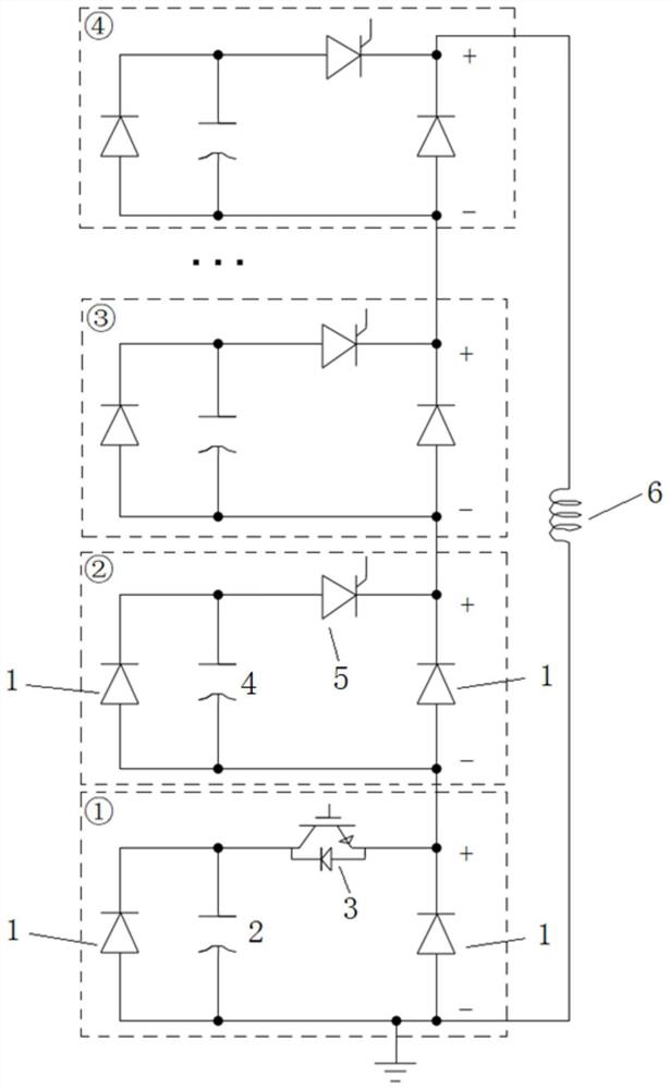
[0042] like figure 2 As shown, the difference between this embodiment and embodiment 1 is:

[0043] The number of high-voltage modules is several, and the high-voltage modules are connected in series, that is, the positive output point of the first high-voltage module is connected to the negative output point of the next high-voltage module, and so on.

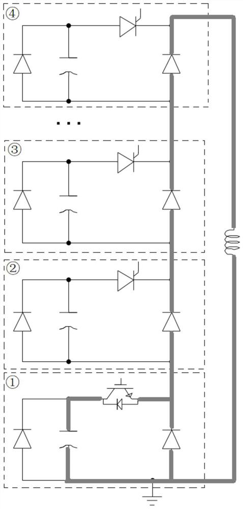
[0044] image 3 , Figure 4 , Figure 5 The medium dark thick line is the current path.

[0045] image 3 It is mainly a schematic diagram of the current path when flat-top current is generated. The thyristors SCR5 of the high-voltage module are all turned off, and the insulated-gate bipolar transistor IGBT3 of the low-voltage module works in a closed-loop modulation state at a certain frequency. When the insulated-gate bipolar transistor IGBT3 is turned on, the capacitor 2. Provide current for the inductive load. When the insulated gate bipolar transistor IGBT3 is turned off, the second diode 1 of the low-voltage module...

Embodiment 1

[0057] The function of the anti-parallel diodes of all capacitors in Embodiment 1 and Embodiment 2 is to prevent the capacitors from being reversely charged. The low-voltage module is closed-loop control, and a current sensor should be added to measure the load current as feedback. The high-voltage module is open-loop control, and the opening signal is the rising edge of the current reference value.

[0058] Image 6 It is a schematic diagram of the effect of the pulse ladder current of the above scheme:

[0059] Point O in the figure represents the starting point of the waveform, that is, at time 0, point A is the starting point of the first current platform, point B is the end point of the first current platform, AB current is I1, point C is the starting point of the second current platform, Point D is the end point of the second current platform, the CD segment current is I2, point E is the starting point of the third current platform, point F is the end point of the third...


PUM


Abstract

The invention belongs to the technical field of power electronics, and relates to a capacitor energy storage type pulse step current generating power supply. The power supply comprises a low-voltage module, a high-voltage module and an inductive load; a positive output point of the low-voltage module is connected with a negative output point of the high-voltage module; the inductive load is connected between the negative output point of the low-voltage module and the positive output point of the high-voltage module; the low-voltage module comprises two diodes, a high-capacity low-voltage capacitor and an insulated gate bipolar transistor (IGBT); and the high-voltage module comprises two diodes, a small-capacity high-voltage capacitor and a thyristor SCR. According to the power supply of the invention, step pulse current can be provided, the stability of flat-top current is higher, and the current and duration of each step are adjustable.

Description

technical field [0001] The invention belongs to the technical field of power electronics, and in particular relates to a capacitive energy storage type pulse ladder current generating power supply. Background technique [0002] The toroidal magnetic field coil is one of the main components of the tokamak device. The coil provides strong toroidal magnetic field confinement and stable plasma for the device. Therefore, the load of the toroidal magnetic field coil power supply is the coil, which is equivalent to an inductance. A spherical tokamak refers to a tokamak device with a ring diameter ratio of less than 1.5, usually using a cheap and flexible capacitor bank to store energy. Uncontrolled discharge can only generate a current flat top, and cannot generate a stepped pulse current. Contents of the invention [0003] Aiming at the above-mentioned prior art, the present invention proposes a closed-loop control capacitive energy storage type toroidal field magnetic field co...

Claims


Application Information

Patent Timeline
Patent Type & Authority Applications(China)
IPC IPC(8): H02M3/07
CPCH02M3/073
Inventor 陈俊宏徐玉麟宣伟民李维斌王英翘姚列英郑雪张潇鹏戢洋夏于洋叶强邓茂才张建甘辉金庆华陈勇范臻圆
Owner SOUTHWESTERN INST OF PHYSICS
Why Eureka
Try Eureka