Radar device
A technology of radar device and shielding shell, which is applied to measurement devices, antennas, instruments, etc., can solve problems such as the inability to fully suppress the noise floor, and achieve the effect of efficient emission
- Summary
- Abstract
- Description
- Claims
- Application Information
AI Technical Summary
Problems solved by technology
Method used
Image

Examples
no. 1 approach >
[0022] 1. Structure of the radar device 1
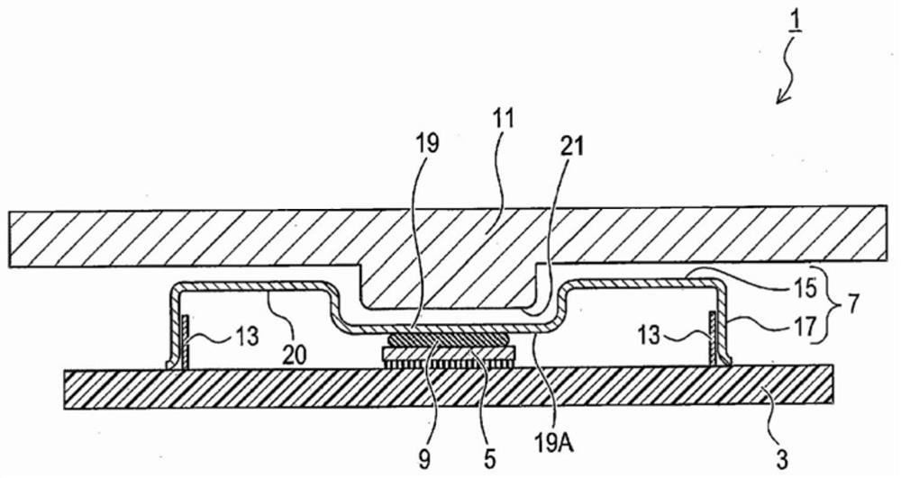
[0023] based on Figure 1 ~ Figure 3 The configuration of the radar device 1 will be described. The radar device 1 is, for example, a vehicle-mounted device. The radar device 1 can be used, for example, in advanced driver assistance systems, automatic driving, and the like. The radar device 1 is, for example, a millimeter-wave radar.
[0024] Such as figure 1 As shown, the radar device 1 includes a substrate 3 , an MMIC 5 , a shield case 7 , a radio wave absorbing heat dissipation gel 9 , and a metal frame 11 . The MMIC 5 is mounted on the substrate 3 . MMIC5 corresponds to high-frequency IC. The substrate 3 is provided with a case receiving portion 13 . The case receiving portion 13 is a wall-shaped member arranged to surround the MMIC 5 . The housing receiver 13 is made of metal.
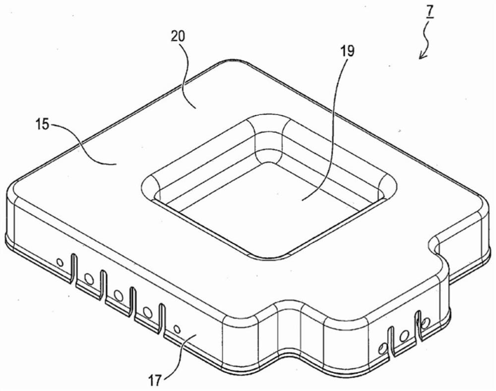
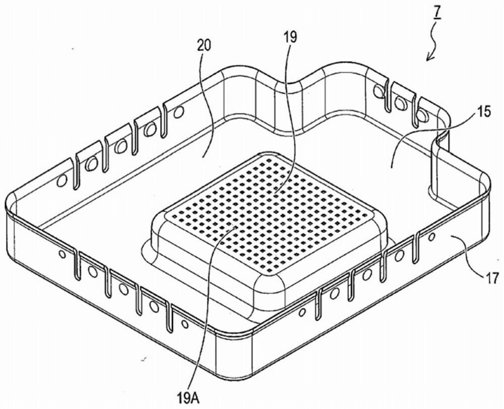
[0025] Such as Figure 1 ~ Figure 3 As shown, the shield case 7 is a box-shaped member with an opening on the side of the substrate 3 . The s...
no. 2 approach >
[0046] 1. Differences from the first embodiment
[0047] Since the basic configuration of the second embodiment is the same as that of the first embodiment, different points will be described below. In addition, the same code|symbol as 1st Embodiment represents the same structure, refer to the previous description.
[0048] In the first embodiment described above, there is no component between the convex portion 19 and the convex portion 21 . In contrast, in the second embodiment, as Figure 4 As shown, the point where the radio wave absorbing heat dissipation gel 23 is filled between the convex portion 19 and the convex portion 21 is different from the first embodiment.
[0049] The radio wave absorbing heat dissipation gel 23 has the same composition as the radio wave absorbing heat dissipation gel 9 . The radio wave absorbing heat radiation gel 23 corresponds to heat radiation gel. The radio wave absorbing heat radiation gel 23 is in contact with the convex portion 19 and...
no. 3 approach >
[0055] 1. Differences from the first embodiment
[0056] Since the basic configuration of the third embodiment is the same as that of the first embodiment, different points will be described below. In addition, the same code|symbol as 1st Embodiment represents the same structure, refer to the previous description.
[0057] In the first embodiment described above, no components are attached to the peripheral portion 20 . In contrast, in the third embodiment, as Figure 5 , Figure 6 As shown, the point that the radio wave absorber 25 is provided on the inner surface of the peripheral portion 20 is different from the first embodiment.
[0058] Such as Figure 6 As shown, the radio wave absorber 25 is disposed so as to surround the convex portion 19 . The radio wave absorber 25 is disposed so as to surround the MMIC 5 when viewed in the thickness direction of the substrate 3 . The radio wave absorber 25 contains, for example, a filler for radio wave absorption. As a filler...
PUM
| Property | Measurement | Unit |
|---|---|---|
| Thermal conductivity | aaaaa | aaaaa |
Abstract
Description
Claims
Application Information