Rapid cooling equipment for sintered powder metallurgy manufactured product

A rapid cooling and powder metallurgy technology, applied in the field of cooling equipment, can solve the problems of long cooling time and low efficiency, and achieve the effect of improving work efficiency

Pending Publication Date: 2022-03-01
肖英梅
View PDF10 Cites 2 Cited by
  • Summary
  • Abstract
  • Description
  • Claims
  • Application Information

AI Technical Summary

Problems solved by technology

[0005] In order to overcome the shortcomings of natural cooling by air, long cooling time and low efficiency, the purpose of the present invention is to provide a fast cooling equipment for powder metallurgy products after sintering with good cooling effect and convenient operation

Method used


Image

  • Rapid cooling equipment for sintered powder metallurgy manufactured product
  • Rapid cooling equipment for sintered powder metallurgy manufactured product
  • Rapid cooling equipment for sintered powder metallurgy manufactured product

Examples


Embodiment 1

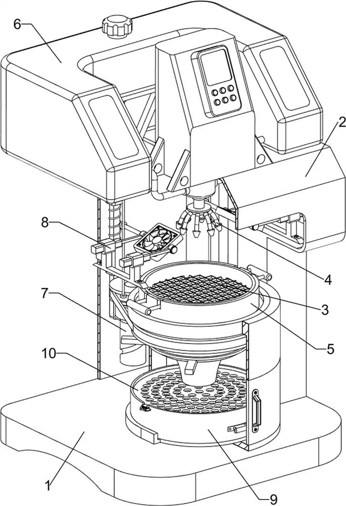
[0030] A rapid cooling equipment for powder metallurgy products after sintering, such as Figure 1-4 As shown, it includes a base 1, a casing 2, a placement net 3, a nozzle 4, a placement assembly 5 and a water spray assembly 6, the upper rear side of the base 1 is provided with a casing 2, the upper middle of the base 1 is provided with a placement assembly 5, and the placement assembly 5 A placement net 3 is placed on it, and a water spray assembly 6 is provided on the upper side of the shell 2, and a nozzle 4 is provided on the water spray assembly 6.

[0031] The placement assembly 5 includes a support frame 501, a rotating cylinder 502, a handle 503 and a frame door 504. The upper middle part of the base 1 is provided with a support frame 501, and the upper side of the support frame 501 is rotatably provided with a rotating cylinder 502. The rotating cylinder 502 The upper side is placed with placing net 3, and placing net 3 left and right sides is provided with grip 503,...

Embodiment 2

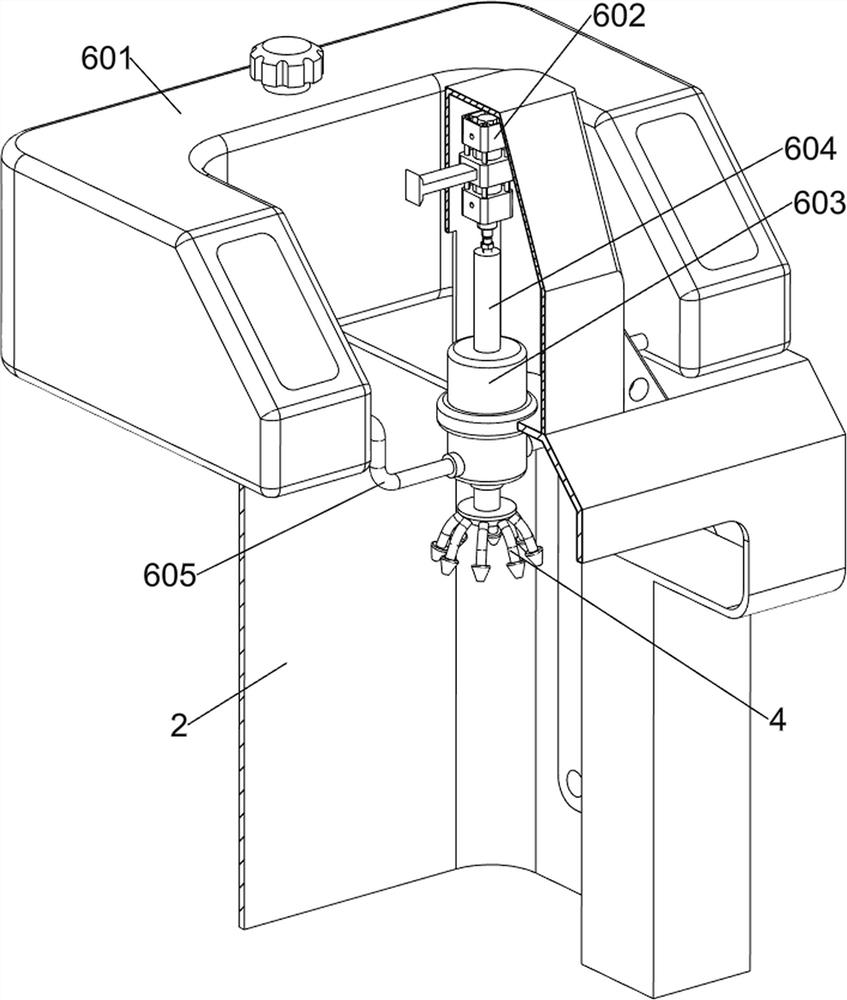
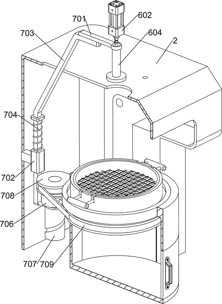
[0035] On the basis of Example 1, such as Figure 5-10 As shown, a rotating assembly 7 is also included, and the rotating assembly 7 includes a pressing rod 701, a guide block 702, a first sliding rod 703, a first spring 704, a first supporting block 706, a groove cylinder 707, a transmission wheel 708 and a transmission belt 709 , the upper rear side of the piston rod 604 is provided with a pressure rod 701, the inner rear side of the casing 2 is provided with a guide block 702, and the guide block 702 is slidably provided with a first slide rod 703, and the first slide rod 703 and the pressure rod 701 are mutually Cooperate, the first spring 704 is connected between the first slide bar 703 and the guide block 702, the first spring 704 is sleeved on the first slide bar 703, the support frame 501 rear side is provided with the first support block 706, the first support block 706 is provided with a grooved cylinder 707 in a rotating manner, and the grooved cylinder 707 cooperat...


PUM


Abstract

The invention relates to cooling equipment, in particular to rapid cooling equipment for sintered powder metallurgy manufactured products. The invention aims to provide the rapid cooling equipment for the sintered powder metallurgy manufactured product, which is good in cooling effect and convenient to operate. According to the technical scheme, the rapid cooling equipment for the sintered powder metallurgy manufactured product comprises a base; the shell is arranged on one side of the base; the placing assembly is arranged at the upper middle part of the base; the placing net is placed on the placing assembly; the water spraying assembly is arranged on the upper side of the shell; and the spray head is arranged on the water spraying assembly. When the piston rod moves upwards, cooling liquid in the water tank can enter the piston cylinder through the water inlet pipe, and when the piston rod moves downwards, the cooling liquid in the piston cylinder can be sprayed to the metallurgical product through the spray head, so that the metallurgical product is rapidly cooled, and the working efficiency of people is improved.

Description

technical field [0001] The invention relates to a cooling device, in particular to a rapid cooling device for a powder metallurgy manufactured product after sintering. Background technique [0002] Powder metallurgy is a process technology for producing metal powder or using metal powder as raw material, forming and sintering to manufacture metal materials, composite materials and various types of products. [0003] The sintering of powder metallurgy products is to sinter and harden the pressed powder metallurgy products in a sintering furnace whose temperature is lower than the melting point of the main part. After the powder metallurgy products are sintered at high temperature in the sintering furnace, they are transported from the sintering furnace to the cooling box for cooling. The existing technology is to send the sintered powder metallurgy parts out of the sintering furnace and let the air cool naturally, which takes a long time for cooling. low efficiency. [0004...

Claims


Application Information

Patent Timeline
Patent Type & Authority Applications(China)
IPC IPC(8): B22F3/24
CPCB22F3/003B22F3/24
Inventor 肖英梅
Owner 肖英梅
Why Eureka
Try Eureka