Paperboard cutter for carton packaging box

A packaging box and cutter technology, used in paper/cardboard containers, packaging, transportation and packaging, etc., can solve the problems of high resistance to moving the blade down, poor cutting effect, and large consumption of blade, so as to reduce the cutting resistance. , Improve the cutting efficiency and the effect of efficient cutting

Pending Publication Date: 2022-03-01
曾大兵
View PDF0 Cites 0 Cited by
  • Summary
  • Abstract
  • Description
  • Claims
  • Application Information

AI Technical Summary

Problems solved by technology

[0004] The object of the present invention is to provide a cardboard cutter for carton packaging boxes to solve the above-mentioned background technology. In order to ensure the processing efficiency, the cardboard will be cut with a knife plate that moves up and down after accumulating to a certain thickness, but the thickness of the cardboard If it is too high, the resistance to the downward movement of the knife plate will be greater and the hydraulic pressure required for the cutting operation will be greater. The cutting method of cutting the knife plate vertically up and down will consume too much of the knife plate and the cutting effect will not be good.

Method used


Image

  • Paperboard cutter for carton packaging box
  • Paperboard cutter for carton packaging box
  • Paperboard cutter for carton packaging box

Examples


Embodiment 1

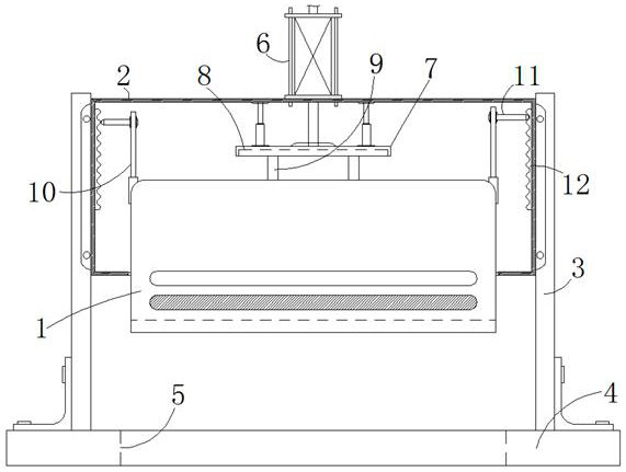
[0030] Such as figure 1 As shown, the cardboard cutter includes a knife plate 1, the knife plate 1 is slid up and down and installed on the lower end surface of the shell 2, and the side of the shell 2 is fixed on the platform 4 through the column 3, and the platform 4 is provided with a knife plate 1 corresponding up and down. A hydraulic rod 6 is installed on the casing 2, and the output end of the hydraulic rod 6 is connected with the upper end surface of the knife plate 1 through the connecting rod 7 and the vertical rod 9, and also includes a chute 8, which is set on the lower end surface of the connecting rod 7 The top of the chute 8 and the vertical bar 9 is slidingly connected, and the bottom end of the vertical bar 9 is fixedly connected with the knife plate 1; the stacked cardboard is located between the knife plate 1 and the platform 4, and the width of the cardboard is smaller than that of the knife plate 1 Length, when the hydraulic rod 6 was running, the knife pl...

Embodiment 2

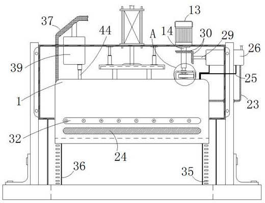
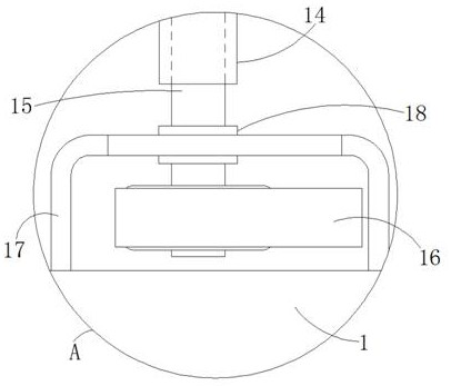
[0033] Such as figure 2 and image 3 As shown, the difference from Embodiment 1 is that in this embodiment the vibrating mechanism is composed of a motor 13, a vertical cylinder 14, a vertical shaft 15 and a cam plate 16, and the top of the vertical cylinder 14 with a square slot and the top of the motor 13 are provided inside. The output end is connected, and the inside of the vertical tube 14 is vertically slidingly connected with the vertical shaft 15 below it. The bottom end of the vertical shaft 15 is fixed with a horizontally distributed cam plate 16, and the right side surface of the cam plate 16 is connected to the inner wall of the vibration box 17. contact, and the top wall of the vibrating box 17 and the slider 18 are horizontally slidingly connected, and the slider 18 is rotatably connected to the vertical shaft 15 passing through, the motor 13 drives the cam plate 16 to rotate, and the eccentrically installed cam plate 16 drives and fixes the The vibrating box 1...


PUM


Abstract

The paperboard cutter comprises a cutting board, the cutting board is installed on the lower end face of a shell in an up-down sliding mode, the side of the shell is fixed to a platform through a stand column, the platform is provided with a cutting groove corresponding to the cutting board in an up-down mode, and a hydraulic rod is installed on the shell; the output end of the hydraulic rod is connected with the upper end face of the cutting board through a connecting rod and a vertical rod, the sliding groove formed in the lower end face of the connecting rod is slidably connected with the top end of the vertical rod, and the bottom end of the vertical rod is fixedly connected with the cutting board. According to the paperboard cutter of the carton packaging box, the vibration mechanism is used for enabling the cutting board to move vertically up and down and to be in a left-right high-frequency moving state at the same time, so that a water mist spraying effect generated by the same power source is matched, a paperboard is cut more efficiently, the loss of the cutting board is effectively reduced, and the cutting efficiency is improved.

Description

technical field [0001] The invention relates to the technical field of carton processing, in particular to a cardboard cutter for carton packaging boxes. Background technique [0002] As a low-cost packaging equipment, carton is widely used in daily life. Its main structure is composed of cardboard. After the cardboard is processed into rolls, it needs to use the corresponding cutter to cut the cardboard when it needs to be made into a carton. After that, indentation and forming processing are carried out. Some cardboards are cut one by one, and some cardboards are stacked up and down, and then the cutter is used for uniform trimming and cutting. The cutter applied to the latter cutting method is actually used. The following problems still exist: [0003] In order to ensure the processing efficiency, the cardboard will be cut with a knife plate that moves up and down after accumulating to a certain thickness, but the thickness of the back cardboard is too high, resulting in...

Claims


Application Information

Patent Timeline
Patent Type & Authority Applications(China)
IPC IPC(8): B31B50/20B31B50/22B31B50/74
CPCB31B50/20B31B50/22B31B50/74
Inventor 曾大兵
Owner 曾大兵
Why Eureka
Try Eureka