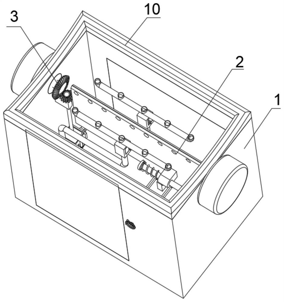
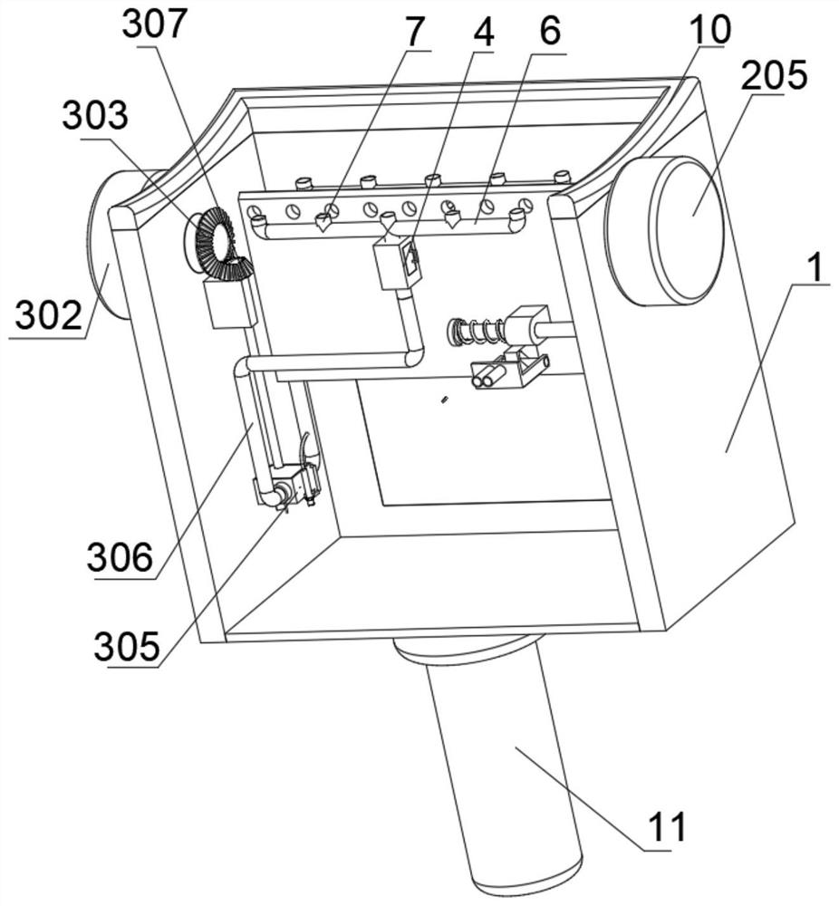
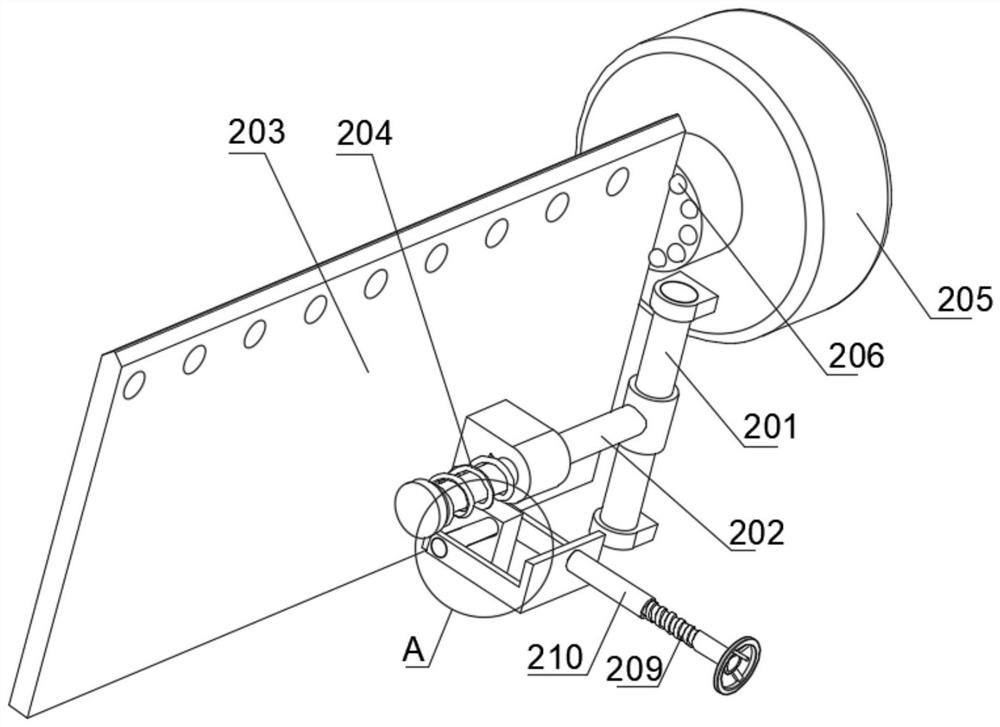
High-temperature roller scraping tool

A scraping roller and high temperature technology, which is applied in the field of diaphragm production tooling, can solve problems affecting film forming, temperature changes of conveyor belt rollers, and large safety hazards, so as to avoid temperature drop, improve cleaning effect, and reduce heat loss.

Active Publication Date: 2022-03-01
HUIQIANG WUHAN NEW ENERGY MATERIAL TECH
View PDF7 Cites 3 Cited by
  • Summary
  • Abstract
  • Description
  • Claims
  • Application Information

AI Technical Summary

Problems solved by technology

[0003] In the existing technology, during the production process of the diaphragm, the conveying roller needs to maintain a relatively high temperature, so as to ensure the forming quality of the diaphragm. On the other hand, dust, film debris and other debris are easy to stick to the conveying roller. If it is not cleaned in time, it will easily lead to deformation and bumps in the film during the forming process. However, at this time, the conveying roller is in a high temperature state. As a result, the temperature of the conveyor belt roller changes, which affects the forming of the film. Therefore, we propose a high-temperature scraping roller tool to solve the above problems

Method used


Image

  • High-temperature roller scraping tool
  • High-temperature roller scraping tool
  • High-temperature roller scraping tool

Examples


Embodiment Construction

[0029] The following will clearly and completely describe the technical solutions in the embodiments of the present invention with reference to the accompanying drawings in the embodiments of the present invention. Obviously, the described embodiments are only some, not all, embodiments of the present invention.

[0030] In describing the present invention, it should be understood that the terms "upper", "lower", "front", "rear", "left", "right", "top", "bottom", "inner", " The orientation or positional relationship indicated by "outside", etc. is based on the orientation or positional relationship shown in the drawings, and is only for the convenience of describing the present invention and simplifying the description, rather than indicating or implying that the referred device or element must have a specific orientation, so as to Specific orientation configurations and operations, therefore, are not to be construed as limitations on the invention.

[0031] refer to Figure ...


PUM


Abstract

The tool comprises a shell, an opening is fixedly connected to the upper end of the shell, an arc-shaped groove is formed in the upper end of the shell, a scraping mechanism is arranged in the shell, and a cleaning assembly is arranged in the shell. The invention relates to the technical field of diaphragm production tools, the shell is arranged to be matched with the cleaning assembly, a scraping mechanism is utilized to clean the side wall of a conveying roller, meanwhile, a first driving wheel is utilized to be matched with an upper bevel gear and a lower bevel gear to drive fan blades to rotate, an air pipe close to sundries can adsorb the sundries, and then the cleaning effect is improved; and as the air can only circulate in the shell, heat loss is reduced, and the temperature of the cleaned area of the conveying belt is prevented from being reduced when the conveying rollers are cleaned, so that the production quality of a film is prevented from being influenced when the conveying rollers are cleaned.

Description

technical field [0001] The invention relates to the technical field of diaphragm production tooling, in particular to a high-temperature scraping roller tool. Background technique [0002] Roller generally refers to something that can rotate cylindrically on the machine. As a common production equipment in industry, roller is widely used in the transmission of objects, especially the processing and transportation of flexible materials such as cloth and film, as well as the extrusion molding of some materials. It can also be used with transmission equipment such as conveyor belts. [0003] In the existing technology, during the production process of the diaphragm, the conveying roller needs to maintain a relatively high temperature, so as to ensure the forming quality of the diaphragm. On the other hand, dust, film debris and other debris are easy to stick to the conveying roller. If it is not cleaned in time, it will easily lead to deformation and bumps in the film during t...

Claims


Application Information

Patent Timeline
Patent Type & Authority Applications(China)
IPC IPC(8): B65G45/14B65G45/26B65G69/20B08B1/02B08B5/04
CPCB65G45/14B65G45/105B65G45/26B65G69/20B08B1/02B08B1/005B08B5/043
Inventor 王红兵李雷马兴玉周振新杨招边红兵付凯陈勇
Owner HUIQIANG WUHAN NEW ENERGY MATERIAL TECH
Why Eureka
Try Eureka