Fishing port wharf structure suitable for different water levels and using method of fishing port wharf structure

A fishing port and wharf technology, applied in the field of port water conservancy projects, can solve the problems of high rental maintenance and use costs, unfavorable modular production and complex component structures, etc., achieve low rental maintenance and use costs, and facilitate modular production and manufacturing. The effect of reasonable structural design

Inactive Publication Date: 2022-03-01
李振国
View PDF1 Cites 0 Cited by
  • Summary
  • Abstract
  • Description
  • Claims
  • Application Information

AI Technical Summary

Problems solved by technology

[0004] However, this kind of fishing port wharf structure has disadvantages when it is used. First, it adopts a fixed structure without adjustable functions, which cannot meet the berthing needs of different small fishing boats, nor can it meet the subdivision leasing requirements of leasing fishing port wharfs; The structure of its components is complex, which is not conducive to modular production and manufacturing, and the cost of leasing, maintenance and use is high

Method used


Image

  • Fishing port wharf structure suitable for different water levels and using method of fishing port wharf structure
  • Fishing port wharf structure suitable for different water levels and using method of fishing port wharf structure
  • Fishing port wharf structure suitable for different water levels and using method of fishing port wharf structure

Examples


Embodiment 1

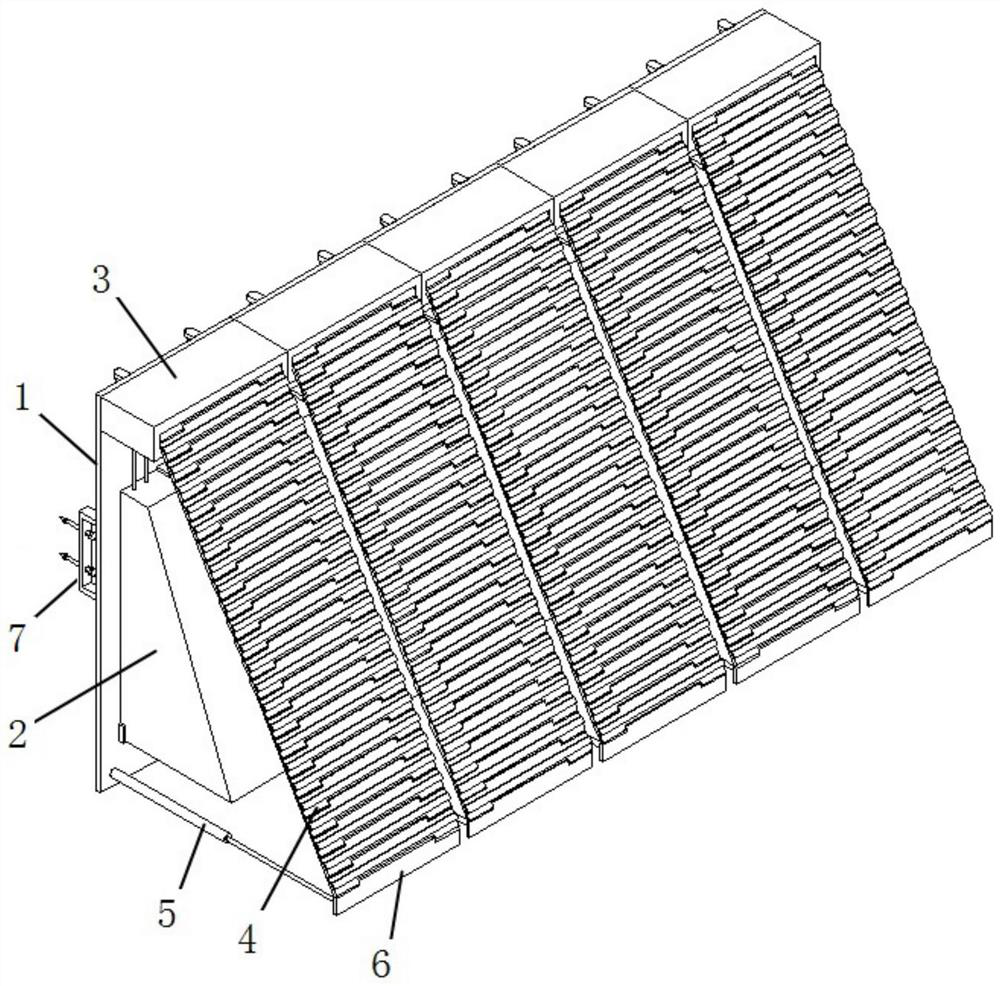
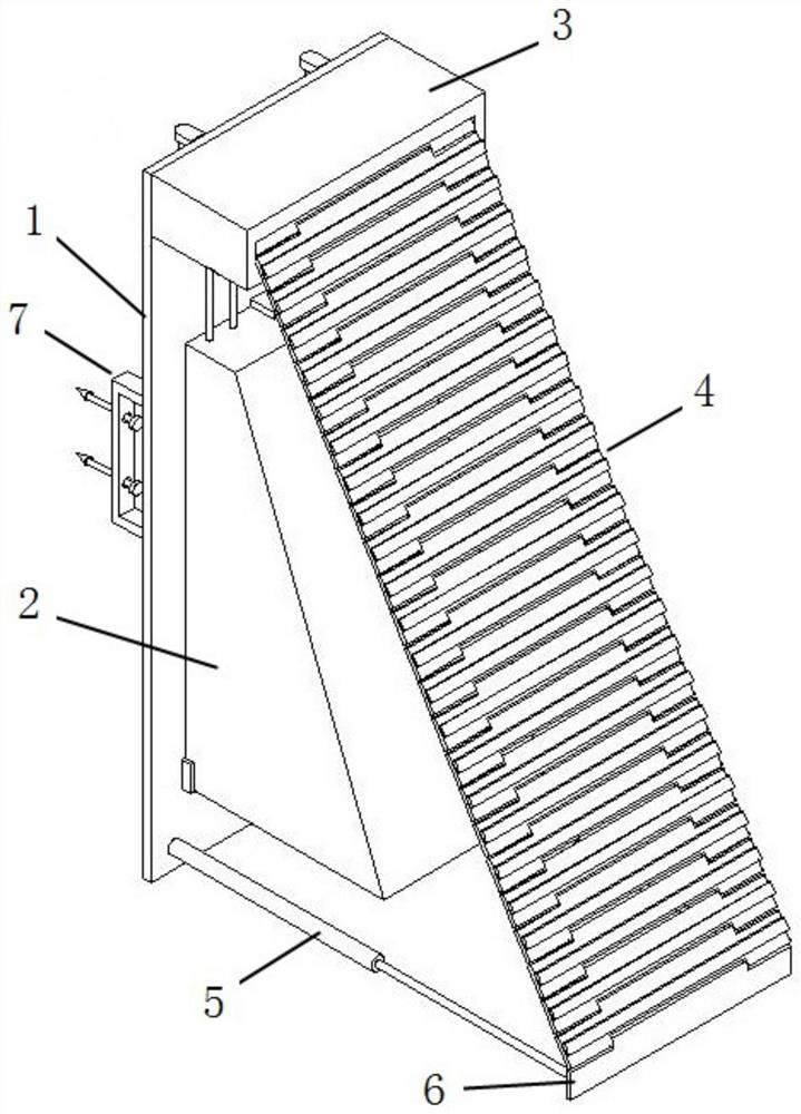
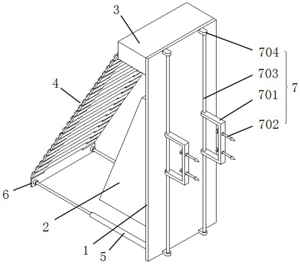
[0034] see Figure 1-6 As shown, this embodiment is a fishing port wharf structure suitable for different water levels. The fishing port wharf structure includes several modular docking units. Type docking plate 4, telescopic rod 5, limit base plate 6 and self-adjusting guiding mechanism 7.

[0035] In this embodiment, a floating airbag 2 is connected to the outer middle part of the support vertical plate 1, and a storage box 3 is fixed on the outer top of the support vertical plate 1. The storage box 3 is provided with a storage area 301 for installing the rolling assembly and a storage area 301 for installing The air pump installation area 302 of the buoyancy adjustment air pump, the buoyancy adjustment air pump communicates with the floating air bag 2 through the air pipeline, and the reel of the winding and unwinding assembly is wound and connected with a roller shutter type docking plate 4 . The outer end of the roller shutter-type docking plate 4 is connected with a lim...

Embodiment 2

[0043] The structure and application of this embodiment are basically the same as those of Embodiment 1, the difference being that the telescopic rod 5 is an electric telescopic rod.

Embodiment 3

[0045] The structure and application of this embodiment are basically the same as those of the first embodiment, the difference being that the support vertical board 1 is fixedly connected to the floating airbag 2 by binding.


PUM


Abstract

The invention belongs to the technical field of port water conservancy projects, and particularly relates to a fishing port wharf structure suitable for different water levels and a using method of the fishing port wharf structure. The modularized parking unit comprises a supporting vertical plate, a floating air bag, a storage box, a roller shutter type parking plate, a telescopic rod, a limiting bottom plate and a self-adjusting guide mechanism, the floating air bag is connected to the middle of the outer side of the supporting vertical plate, the storage box is fixed to the top of the supporting vertical plate, the telescopic rod is installed at the bottom of the supporting vertical plate, and a storage area and an air pump installation area are arranged in the storage box. The buoyancy adjusting air pump is communicated with the floating air bag, a rolling shaft of the rolling and unrolling assembly is connected with a roller shutter type stopping plate in a winding mode, and a self-adjusting guide mechanism is installed on the inner side of the supporting vertical plate. A plurality of independent modularized parking units are designed to form the fishing port wharf structure, each modularized parking unit serves as a leasing unit, the parking requirements of different small fishing boats are met, and meanwhile the partition leasing requirement of a leasing type fishing port wharf is met.

Description

technical field [0001] The invention belongs to the technical field of port water conservancy engineering, and in particular relates to a fishing port wharf structure suitable for different water levels and an application method thereof. Background technique [0002] At present, in many areas and river ports in our country, the water level rises and falls rapidly. Faced with different water levels, with the development of cascaded hydropower energy resources in major rivers and river systems, the high gorge comes out of Pinghu Lake, forming many excellent deep water channels and reservoirs. Lake area water body and water surface resources. At the same time, fundamental changes have taken place in the hydrological and geological conditions of the lake and reservoir area. The main hydrological features are large and frequent changes in water level; For the disembarkation and return of goods to the shore, the wharf structure adapting to different water levels in the prior art ...

Claims


Application Information

Patent Timeline
Patent Type & Authority Applications(China)
IPC IPC(8): E02B3/06E02D5/74
CPCE02B3/068E02B3/064E02D5/74Y02A10/11
Inventor 李振国
Owner 李振国
Why Eureka
Try Eureka