Gas well gas and speed increasing and water atomizing device

A technology of water atomization and gas well, applied in the direction of injection device, injection device, liquid injection device, etc., can solve the problems of low recovery rate, small liquid drainage capacity, high safety and reliability requirements, etc.

Active Publication Date: 2022-03-01
SOUTHWEST PETROLEUM UNIV
View PDF19 Cites 0 Cited by
  • Summary
  • Abstract
  • Description
  • Claims
  • Application Information

AI Technical Summary

Problems solved by technology

Among them, although the preferred tubing string drainage gas production method is simple, it needs to continuously adjust the gas well string according to the production status of the gas well, and the size of the tubing is too large or too small, which will have an adverse effect on production; the bubble drainage process is easy to implement and effective Fast, but the liquid drainage capacity is small and continuous injection is required, which increases labor costs and workload; the gas lift drainage and gas recovery process is not limited by factors such as well deviation, well depth, hydrogen sulfide, etc., and has a significant increase in production effect, and can be started repeatedly , but high-pressure equipment and high-pressure gas sources are required, and the safety and reliability requirements of high-pressure operation team devices are high; the machine-pumped drainage gas recovery process equipment is simple and reliable, and the process well is not affected by the degree of recovery, and the depletion of gas and water wells can be realized. However, it is greatly affected by factors such as well deviation, well depth, hydrogen sulfide, and pump hanging depth.
[0004] Although the existing drainage gas recovery technology can solve the problem of gas well water production to a certain extent, this technology can only be used for general treatment after the wellbore begins to accumulate fluid in the middle and late stages of gas well production. The adaptability of gas wells is relatively poor, and early water control cannot be realized. Therefore, in view of the actual situation of large water production and low recovery rate faced by gas reservoir exploitation in China at present, a kind of water control can be realized on the one hand. Balance the inflow profile, and at the same time increase the gas flow rate in the middle and later stages of gas well production, and can atomize and separate formation water and discharge it after the gas well produces water. Prolong gas well life and enhance recovery

Method used


Image

  • Gas well gas and speed increasing and water atomizing device
  • Gas well gas and speed increasing and water atomizing device
  • Gas well gas and speed increasing and water atomizing device

Examples


Embodiment Construction

[0016] The present invention will be further described below in conjunction with the accompanying drawings and embodiments.

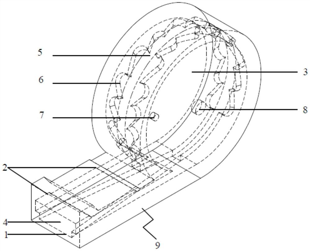
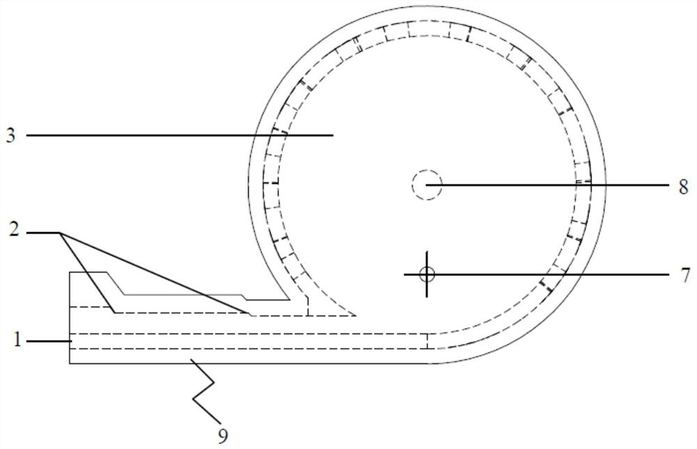
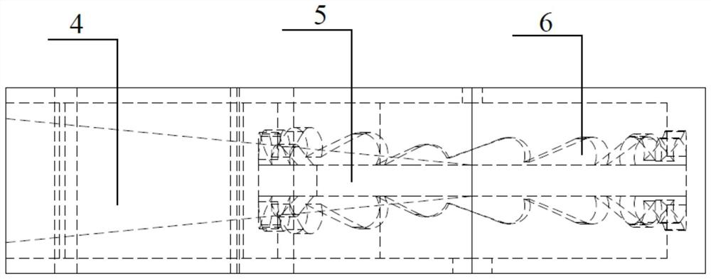
[0017] Such as figure 1 As shown, the embodiment of the present invention provides a gas well gas-increasing speed-up and water atomization device, which may include: a spray chamber inlet 1, an inlet variable diameter pre-acceleration chamber 2, an annular speed-up chamber 3, and a tapered diameter pre-acceleration flow channel 4 , acceleration channel main channel 5, variable diameter speed-up channel 6, atomization outlet 7, air outlet 8, linear pre-acceleration chamber 9; the whole device consists of a linear pre-acceleration chamber 9 and an annular speed-up chamber 3 tangential to it Composition, the inlet 1 of the spray chamber is the direction of fluid inflow, the atomization outlet 7 and the air outlet 8 are the direction of fluid outflow, the atomization outlet 7 and the air outlet 8 are respectively arranged on the two sides of the annular sp...


PUM


Abstract

The device comprises a spraying cavity inlet (1), an inlet reducing pre-acceleration cavity (2), an annular acceleration cavity (3), a reducing pre-acceleration flow channel (4), an acceleration flow channel main flow channel (5), a reducing acceleration flow channel (6), an atomization outlet (7), an airflow outlet (8) and a linear pre-acceleration cavity (9). According to the device, the three-dimensional cavity and built-in flow channel type design is adopted, acceleration of gas-liquid two-phase fluid, especially gas-phase fluid, can be achieved in the device, meanwhile, gas-liquid two-phase separation can be achieved, and the function of liquid-phase fluid atomization and discharging of the device is achieved; the device provided by the invention is suitable for balanced inflow profile before water output of the gas well and drainage after water output of the gas well, realizes control and drainage at the same time, and achieves the purposes of prolonging the service life of the gas well and improving the recovery ratio.

Description

technical field [0001] The invention relates to the technical field of oil and gas field development, a tool used for gas-phase speed-up, gas-liquid separation, and liquid-phase atomization in the process of natural gas exploitation, in particular to a gas well gas-increasing speed-up and water atomization device. Background technique [0002] At present, the gas fields that have been developed in my country mainly rely on the energy of the gas reservoir itself in the early stage of production. Most of them are in the stage of anhydrous gas production. Production and service life have had a great impact; in addition, there are also some gas wells with active formation water at the edge and bottom. During the gas production process, it is easy to cause excessive gas production due to improper control, causing bottom water coning or edge water tongue It will affect the normal gas production of gas wells. [0003] Generally, the production system and method of constant pressure ...

Claims


Application Information

Patent Timeline
IPC IPC(8): E21B43/16
CPCE21B43/168F04F5/10B05B7/02B05B1/34
Inventor 李海涛高素娟聂松杜厚余杨苗马欣
Owner SOUTHWEST PETROLEUM UNIV
Why Eureka
Try Eureka