Optical mirror surface online detection method and detection device

An optical mirror and detection device technology, applied in the field of laser detection, can solve the problems affecting the work and application of lasers, low work efficiency, high maintenance cost, etc., and achieve the effect of easy fine detection and analysis, strong applicability, and small size

Pending Publication Date: 2022-03-01
NANJING INST OF ADVANCED LASER TECH +1
View PDF1 Cites 0 Cited by
  • Summary
  • Abstract
  • Description
  • Claims
  • Application Information

AI Technical Summary

Problems solved by technology

[0002] Optical technology has been widely used in all aspects of military, industry and life, especially with the invention and application of lasers, which has greatly promoted the country's overall scientific and technological productivity and industrial application level. With the development of various optical technologies in various application fields Enlarging and deepening puts forward higher requirements for optical equipment. Device miniaturization, compactness, long life, high reliability, and integration are typical demand characteristics. At the same time, installation and online detection are also important contents, especially for lasers as high-power light source devices. Damage has always been an obstacle to its best performance, and the importance of rapid detection and maintenance is self-evident; the maintenance method of conventional lasers is human eye observation or step-by-step test judgment after shutdown, or dismantling the laser mirror Finally, use the optical lens detection equipment disclosed in CN202010280954.8 for detection; this method has the following disadvantages: 1. Low work efficiency and high maintenance cost; 2. Disassemble the laser for offline detection and then reinstall it. Seriously affect the work and application of the laser

Method used


Image

  • Optical mirror surface online detection method and detection device
  • Optical mirror surface online detection method and detection device
  • Optical mirror surface online detection method and detection device

Examples


Embodiment Construction

[0025] The present invention will be more clearly and completely described below by way of a preferred embodiment with reference to the accompanying drawings, but the present invention is not limited to the scope of the described embodiment.

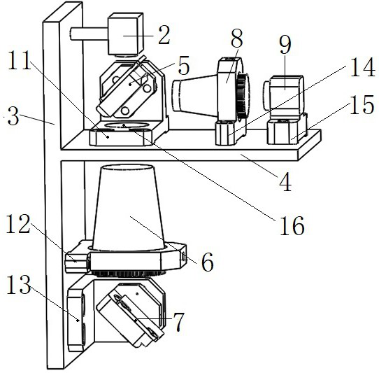
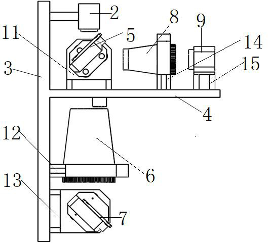
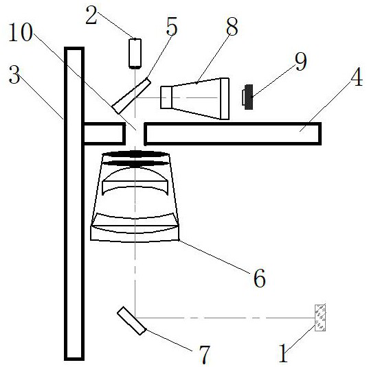
[0026] like image 3 As shown, a kind of optical mirror online detection method provided by the present invention adopts confocal detection method, comprising the following steps:

[0027] S01. Adopt the indicator light source with two modes of thin beam and large spot, adjust the indicator light source to the thin beam mode, take the indicator light emitted by the indicator light source as the reference light, and the incident light path of the indicator light source passes through the beam splitter in sequence before reaching the optical mirror And the zoom lens group, the optical path of the indicator light source coincides with the main optical axis of the zoom lens group; the reflector reflects the incident light path of the indicat...


PUM


Abstract

The invention discloses an on-line detection method and device for an optical mirror surface. The on-line detection method for the optical mirror surface uses a confocal detection principle, an optical mirror surface image is obtained through a zoom lens group, the optical mirror surface image is amplified through an image amplification device, and finally the amplified image is detected, positioned and subjected to damage point calibration. The optical mirror surface online detection device comprises an indication light source, a reflective mirror, a spectroscope, a zoom lens group and an image detection unit, the image detection unit comprises an image amplification device and an image detection assembly, and the spectroscope and the reflective mirror are installed above and below the zoom assembly respectively; the image amplification device and the image detection assembly are sequentially fixed on a reflection light path of the spectroscope; the device performs scanning detection and fine detection on the optical mirror surface at the same time, is high in detection precision, is simple and compact in overall structure, is small in size, and can remarkably improve the detection efficiency of a to-be-detected laser light path.

Description

technical field [0001] The invention relates to the technical field of laser detection, in particular to an online detection method and detection device for an optical mirror surface. Background technique [0002] Optical technology has been widely used in all aspects of military, industry and life, especially with the invention and application of lasers, which has greatly promoted the country's overall scientific and technological productivity and industrial application level. With the development of various optical technologies in various application fields Enlarging and deepening puts forward higher requirements for optical equipment. Device miniaturization, compactness, long life, high reliability, and integration are typical demand characteristics. At the same time, installation and online detection are also important contents, especially for lasers as high-power light source devices. Damage has always been an obstacle to its best performance, and the importance of rapi...

Claims


Application Information

Patent Timeline
IPC IPC(8): G01M11/02G01N21/95
CPCG01M11/02G01N21/95G01N2021/9511
Inventor 王建磊陈明高雅丁建永周军陈卫标
Owner NANJING INST OF ADVANCED LASER TECH
Why Eureka
Try Eureka