
Device and method for testing current-carrying capacity of copper bar

A testing device and flow technology, which is applied to the measuring device, the housing of the measuring device, the parts of the electrical measuring instrument, etc.

Active Publication Date: 2022-03-01
南通昊海电器有限公司
View PDF5 Cites 0 Cited by
  • Summary
  • Abstract
  • Description
  • Claims
  • Application Information

AI Technical Summary

Problems solved by technology

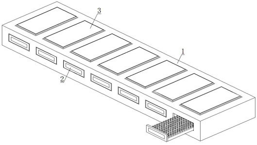
[0005] The object of the present invention is to provide a test device and method for the carrying capacity of copper bars, which solves the problem that the carrying capacity of copper bars in the background technology is mainly determined by three factors: material, cross-sectional area and laying conditions. The current carrying capacity of the copper bar, but in the actual use process, due to the complex use environment, the surface of the copper bar is damaged, and the cross-sectional area of ​​the damaged part is reduced, and the value of the current carrying capacity calculated by ordinary calculation is larger than the actual value of the current carrying capacity , there is a deviation in the numerical test of the ampacity, and it is cumbersome to re-measure the cross-sectional size of the copper bar, and it is not easy to test whether the numerical value of the ampacity of the copper bar meets the standard.

Method used

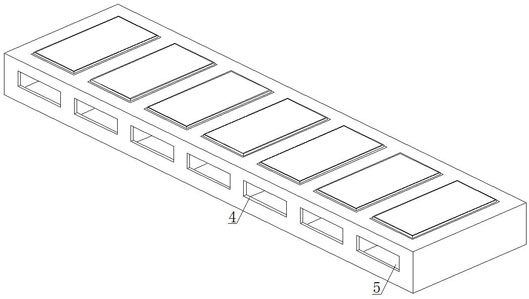

Image

  • Device and method for testing current-carrying capacity of copper bar
  • Device and method for testing current-carrying capacity of copper bar
  • Device and method for testing current-carrying capacity of copper bar

Examples


Embodiment approach

[0049] In order to further and better explain the above-mentioned embodiments, the present invention also provides an embodiment, a test method of a test device for the carrying capacity of a copper bar, comprising the following steps:

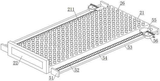
[0050] Step 1: start the drive shaft 564, the disc body 561 makes the top pressure small block 565 drive the limit bar 553 to move to one side, the trapezoidal slider 55 drives the external baffle 22 to disengage from the opening 4, and the supporting test plate 2 as a whole moves from Pulled out from the test cavity 5, the adjusting plate 56 can move along with the trapezoidal slider 55, when the external baffle 22 is loosened, the supporting test plate 2 returns to the test cavity 5 as a whole;

[0051] Step 2: When the supporting test board 2 is pulled out from the test cavity 5, place the copper bar test piece 6 on the upper end of the supporting board 21, start the driving gear 2412, and the two sets of adjusting gears 2413 move closer to ...


PUM


Abstract

The invention discloses a device and a method for testing the current-carrying capacity of a copper bar, belongs to the technical field of the current-carrying capacity of the copper bar, and aims to solve the problem that the re-measurement of the sectional dimension of the copper bar is relatively tedious due to a complicated use environment, damaged surface of the copper bar, reduced sectional area of a damaged part and deviation of a current-carrying capacity value test in the actual use process. According to the invention, the distance between the two groups of opposite measuring probes is measured through laser displacement sensors of the two groups of opposite measuring probes, numerical values measured by a plurality of groups of opposite measuring probes of the bearing plate and the hanging test plate are the thickness of the copper bar, and numerical values measured by a plurality of groups of opposite measuring probes of the connecting side long plate are the width of the copper bar; preliminary buffering is conducted through a second reset spring, an adjusting straight rod drives a jacking ball to extrude a supporting column block, a traction supporting arm rod is pulled upwards through a connecting spring, and then the supporting column block conducts secondary buffering on the jacking ball.

Description

technical field [0001] The invention relates to the technical field of carrying capacity of copper bars, in particular to a testing device and method for carrying capacity of copper bars. Background technique [0002] Copper bars are suitable for electrical engineering such as high and low voltage electrical appliances, switch contacts, power distribution equipment, and bus ducts. They are also widely used in ultra-high current electrolytic smelting projects such as metal smelting, electrochemical plating, and chemical caustic soda. Copper bus bars are one of the copper processing materials. The main varieties, copper busbar has high mechanical properties, good electrical and thermal conductivity, excellent corrosion resistance, electroplating and brazing properties, beautiful and beautiful metallic luster and good forming and processing performance, so it is used to make Various power transmission and transformation, electrical equipment, etc. have been widely used in the f...

Claims


Application Information

Patent Timeline
Patent Type & Authority Applications(China)
IPC IPC(8): G01R31/00G01R1/02G01R1/04G01R1/073
CPCG01R31/00G01R1/02G01R1/04G01R1/07357
Inventor 李家奎徐众羡
Owner 南通昊海电器有限公司
Learn More