
Backlight plate, LED module and electronic equipment

A backlight board and LED array technology, applied in optics, nonlinear optics, printed circuit components, etc., can solve the problems of large area occupied by LED arrays, low efficiency of SMT mounting, and large waste of PCB boards, etc., so as to reduce the use of area, improve shipment yield, and reduce the effect of PCB cost

Pending Publication Date: 2022-03-01
SHENZHEN MTC LIGHTING CO LTD
View PDF0 Cites 2 Cited by
  • Summary
  • Abstract
  • Description
  • Claims
  • Application Information

AI Technical Summary

Problems solved by technology

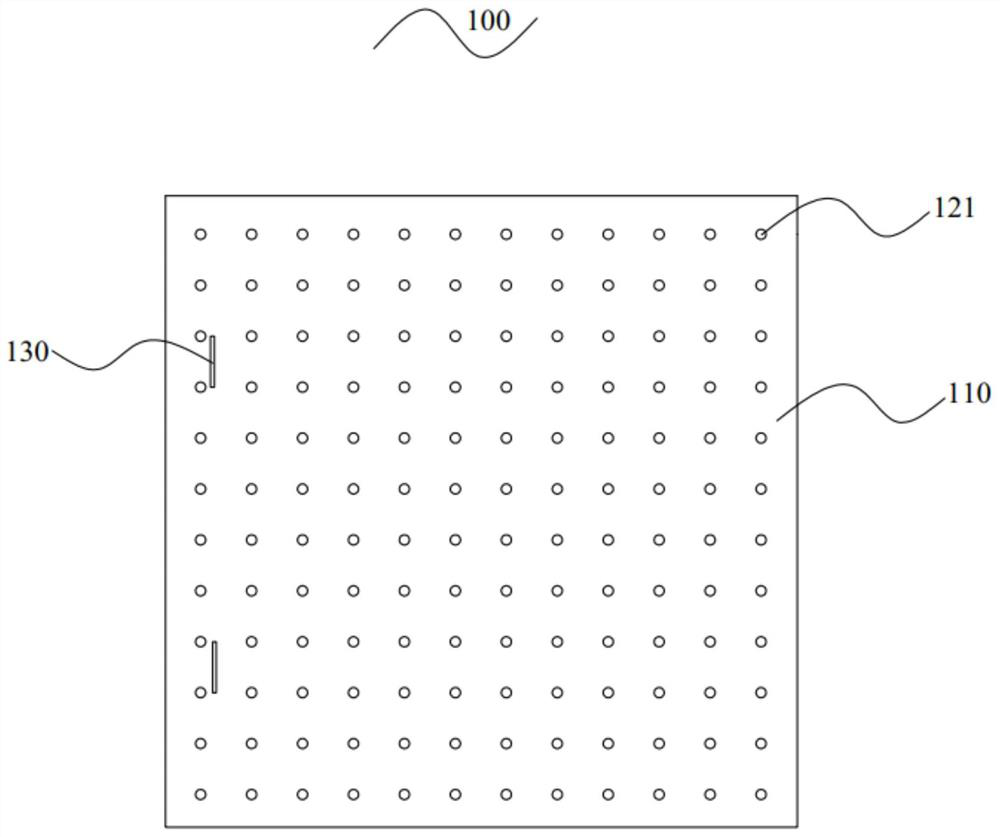
[0004] like figure 1 As shown, the current Mini LED backlight usually uses a square sheet-shaped backplane structure design, while the LED array occupies a large area, and there are problems such as large waste of PCB boards, low effective utilization, high cost, and low SMT mounting efficiency.

Method used


Image

  • Backlight plate, LED module and electronic equipment
  • Backlight plate, LED module and electronic equipment
  • Backlight plate, LED module and electronic equipment

Examples


Embodiment Construction

[0023] In order to facilitate the understanding of the present invention, the present invention will be described more fully below with reference to the associated drawings. Several embodiments of the invention are shown in the drawings. However, the present invention can be embodied in many different forms and is not limited to the embodiments described herein. Rather, these embodiments are provided so that the disclosure of the present invention will be thorough and complete.

[0024] It should be noted that when an element is referred to as being “fixed on” another element, it may be directly on the other element or there may be an intervening element. When an element is referred to as being "connected to" another element, it can be directly connected to the other element or intervening elements may also be present. The terms "vertical," "horizontal," "left," "right," and similar expressions are used herein for purposes of illustration only.

[0025] Unless otherwise def...


PUM


Abstract

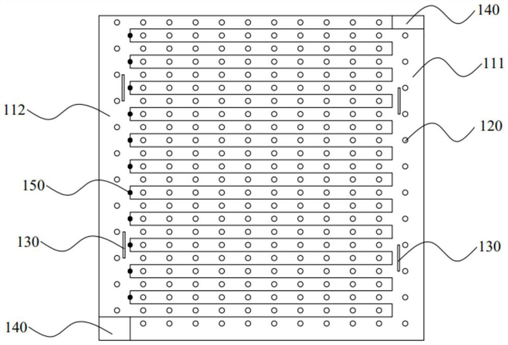
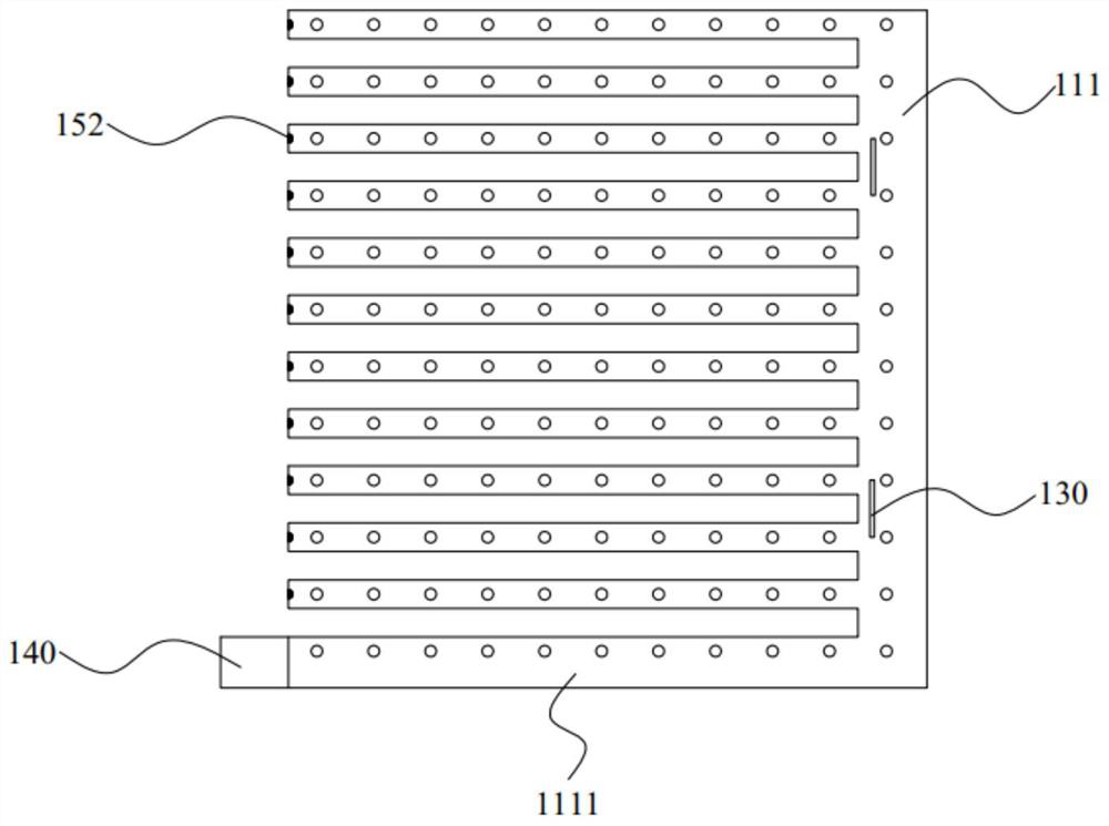
The invention provides a backlight plate, an LED module and electronic equipment, the backlight plate comprises a PCB and an LED array, the PCB comprises a first plate body and a second plate body, the first plate body and the second plate body are arranged in a harpoon structure, one side of the first plate body extends towards the second plate body to form a first harpoon tooth part, and the other side of the first plate body extends towards the second plate body to form a second harpoon tooth part; one side of the second plate body extends towards the first plate body to form a second harpoon tooth part, and the LED arrays are evenly distributed on the first harpoon tooth part and the second harpoon tooth part. The PCB is arranged to be the first board body and the second board body which are of the harpoon structure, the use area of the board is reduced, the effective utilization rate of the board is increased, and the cost of the PCB is reduced when the LED heat dissipation requirement is met; meanwhile, the harpoon tooth parts are uniformly arranged at intervals, so that the internal stress of the backlight plate is reduced, the warping of the backlight plate is improved, and the shipment yield of a backlight plate factory and the process yield of SMT (Surface Mount Technology) are improved; makeup production is achieved through the first plate body and the second plate body, the distribution number of LEDs is increased, and the production efficiency of a backlight plate factory and the surface mounting efficiency of SMT are improved.

Description

technical field [0001] The invention relates to the technical field of semiconductors, in particular to a backlight panel, an LED module and electronic equipment. Background technique [0002] With the rapid development of the semiconductor industry and the improvement of people's living standards, the LED display industry has experienced long-term development, and the technical route is constantly changing, from traditional LCD+LED backlight to LCD+Mini LED backlight. [0003] 2021 is known as the first year of Mini LED mass production. Many TV terminal brand manufacturers at home and abroad have launched a variety of new products, and the attention of Mini LED backlight products has greatly increased. The main competitor of Mini LED backlight is OLED, which has already entered the high-end TV market first. Facing the price-sensitive consumer market, cost may become the key to the success of Mini LED backlight. However, PCB occupies a large proportion in the cost of Mini L...

Claims


Application Information

Patent Timeline
Patent Type & Authority Applications(China)
IPC IPC(8): G02F1/13357H05K1/14H05K1/18
CPCG02F1/133603G02F1/133628H05K1/14H05K1/18
Inventor 林向和周华黎月德赵靖
Owner SHENZHEN MTC LIGHTING CO LTD
Learn More