Tunnel resistivity modeling method and system based on hybrid grid

A tunnel resistance and hybrid grid technology, applied in geometric CAD, design optimization/simulation, special data processing applications, etc., can solve the problem of high hardware performance and calculation time requirements, large amount of 3D forward and inversion calculation, and can not guarantee numerical values. It can solve the problem of electrode placement uncertainty, meet the requirements of timeliness, and reduce the calculation cost.

Pending Publication Date: 2022-03-01
SHANDONG UNIV
View PDF0 Cites 4 Cited by
  • Summary
  • Abstract
  • Description
  • Claims
  • Application Information

AI Technical Summary

Problems solved by technology
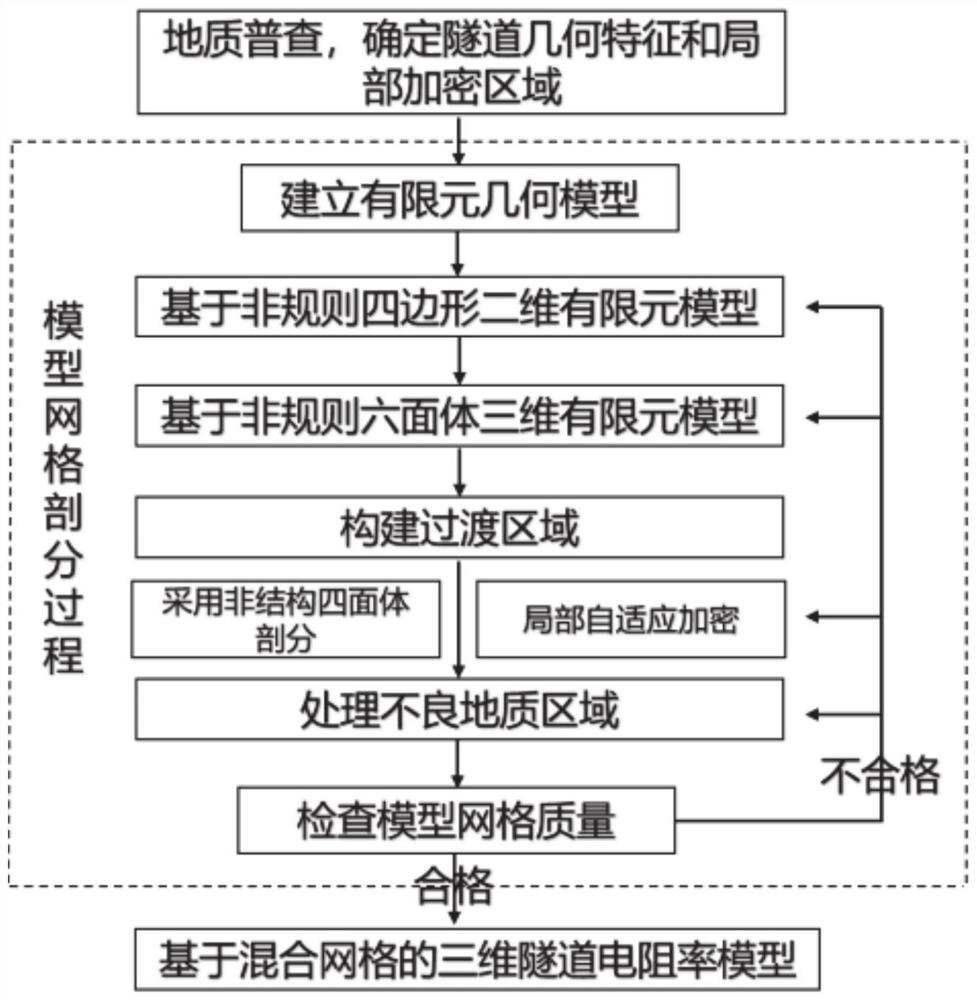
However, the finite element initial mesh does not guarantee that the numerical solution can reach a certain accuracy.
Moreover, the use of t...

Method used


Image

  • Tunnel resistivity modeling method and system based on hybrid grid
  • Tunnel resistivity modeling method and system based on hybrid grid
  • Tunnel resistivity modeling method and system based on hybrid grid

Examples


Embodiment 1

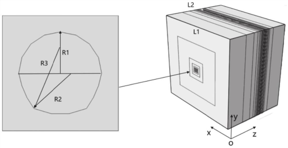
[0050]Taking the horseshoe-shaped tunnel as an example, consulting the engineering geological data and combining the actual detection conditions in the tunnel, it is determined that the actual shape of the tunnel to be modeled is a horseshoe. For side arches with a larger radius, the bottom of the cave is an upward-facing arch, and the connection between the side arch and the bottom arch is rounded with an arc. The power supply and collection electrodes are arranged on the palm face.

[0051] The finite element geometric model is established according to the acquired actual information of the tunnel. like figure 2 As shown, the XOY plane of the model is a square whose side length L1 is 658m, and the YOZ plane of the model is a rectangle whose length L1 is 658m and width L2 is 480m. The roof of the horseshoe-shaped tunnel area is a semicircular arch with a radius R1 of 6.5m, the radius R2 of the side arches on both sides is 10.625m, and the radius R3 of the bottom arch is 8....

Embodiment 2

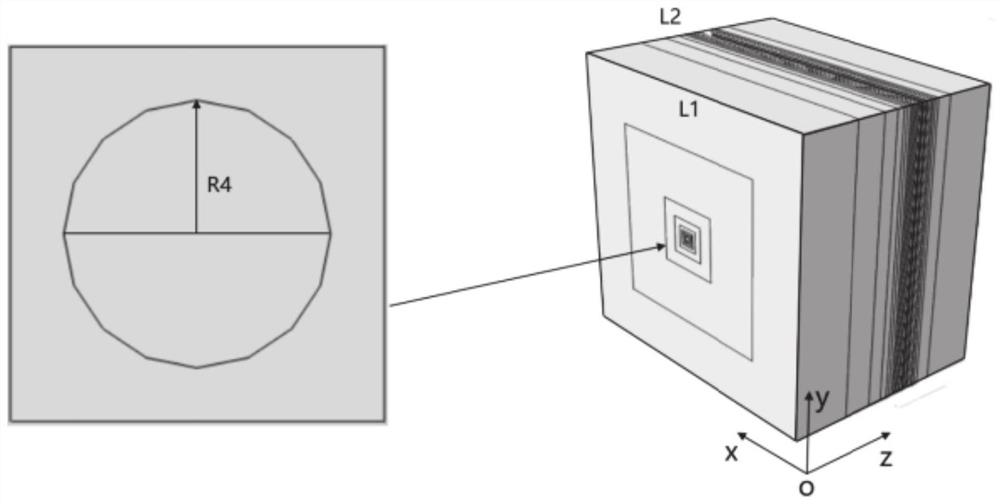
[0056] Taking the circular tunnel as an example, consulting the engineering geological data, combined with the actual detection situation in the tunnel, it is determined that the actual shape of the tunnel to be modeled is circular, and the power supply and collection electrodes are arranged on the tunnel face.

[0057] The finite element geometric model is established according to the acquired actual information of the tunnel. like image 3 As shown, the XOY plane of the model is a square whose side length L1 is 658m, and the YOZ plane of the model is a rectangle whose length L1 is 658m and width L2 is 480m. The circular tunnel area is a circle with a radius R4 of 6m.

[0058] For meshing the finite element geometric model, firstly carry out two-dimensional planar subdivision of the geometric model, and combine the shape and size of the tunnel outline to arrange 8 local seeds on the corresponding sides of the four directions, using irregular quadrilateral Finite element mes...


PUM


Abstract

The invention provides a tunnel resistivity modeling method and system based on a hybrid grid. The method comprises the following steps: determining the physical size, the actual shape, the power supply and acquisition electrode position and the possible unfavorable geological area of a tunnel to be modeled; establishing a finite element geometric model according to the actual shape and size of the tunnel; carrying out mesh generation on the finite element geometric model, carrying out non-structural tetrahedral mesh local encryption subdivision on power supply and acquisition electrode positions and possible unfavorable geological areas, and carrying out mesh generation on other uniform surrounding rock media by adopting an irregular hexahedron to form an optimized model; quality parameters of all units of the optimized model are checked, iterative optimization is carried out on the shapes of the units, so that transition between the units of different sizes and different types is uniform until all the units meet the quality requirements, and the method can well fit a complex structure type and is high in practicability. The discretization error of the model is reduced to a great extent; and the forward modeling precision of an actual tunnel complex environment resistivity method is improved.

Description

technical field [0001] The invention belongs to the technical field of tunnel resistivity modeling, and in particular relates to a tunnel resistivity modeling method and system based on a mixed grid. Background technique [0002] The statements in this section merely provide background information related to the present invention and do not necessarily constitute prior art. [0003] In the advance prediction of tunnel / tunnel adverse geology, the acquisition of water content information of water-bearing structures is particularly important for disaster assessment and early warning. The tunnel resistivity method is based on the difference in resistivity between water-bearing structures and surrounding rocks, and has unique advantages in the advanced detection of water-bearing geological structures. The resistivity method is widely used in engineering for the advanced detection of water-bearing structures in coal mines and tunnels. [0004] The application of numerical simula...

Claims


Application Information

Patent Timeline
IPC IPC(8): G06F30/23G06F30/13
CPCG06F30/23G06F30/13
Inventor 聂利超邓朝阳陈安东宋志成裴文兵郭一凡
Owner SHANDONG UNIV
Why Eureka
Try Eureka