Winding device for transformer core

A transformer core and winding technology, applied in the field of transformers, can solve problems such as uneven distribution of copper wires, inability to fix the iron core, and easy quality problems of the iron core, and achieve simple and convenient operation, improved production quality, and simple and convenient clamping hold a fixed effect

Pending Publication Date: 2022-03-01
PENGLAI POWER SUPPLY CO OF STATE GRID SHANDONG ELECTRIC POWER CO
View PDF0 Cites 5 Cited by
  • Summary
  • Abstract
  • Description
  • Claims
  • Application Information

AI Technical Summary

Problems solved by technology

[0004] The purpose of the present invention is to solve the problem that the existing winding device in the prior art cannot fix the iron core conveniently during the winding process of the iron core, and it is easy to cause the copper wire to be unevenly distributed during the winding process of the copper wire. uniform, resulting in the production of iron cores prone to quality problems, and the proposed winding device for transformer iron core

Method used


Image

  • Winding device for transformer core
  • Winding device for transformer core
  • Winding device for transformer core

Examples


Embodiment 1

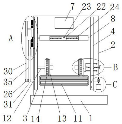
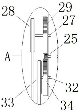
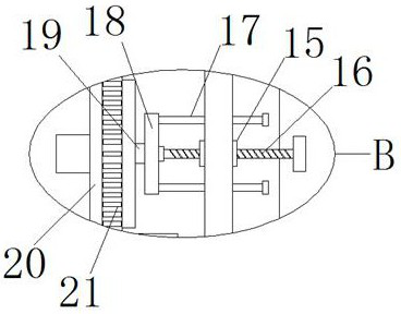
[0027] refer to Figure 1-5 , a winding device for a transformer core, including a base 1, the top of the base 1 is fixedly connected with a riser 2 by welding, and the riser 2 is fixedly connected with a left side plate 3 and a right side plate 4 through welding, and the left side plate 3 The same winding mechanism is set on the right side plate 4, the motor 5 is fixedly installed on the vertical plate 2 by bolts, the output shaft of the motor 5 is welded with a worm 6, the worm 6 cooperates with the winding mechanism, and the left side plate 3 The top is provided with a rotation limiting mechanism, and the right side plate 4 is provided with a rotation extrusion mechanism, the rotation limitation mechanism and the rotation extrusion mechanism cooperate with the winding mechanism, and the vertical plate 2 is fixedly connected with a placement box 7 and a horizontal The plate 8 and the horizontal plate 8 are provided with a reciprocating positioning mechanism, and the reciproc...

Embodiment 2

[0037] The difference from Embodiment 1 is that it includes a base 1, a riser 2 is fixedly connected to the top of the base 1, a left side board 3 and a right side board 4 are fixedly connected to the riser 2, and the left side board 3 and the right side board 4 is provided with the same winding mechanism, a motor 5 is fixedly installed on the vertical plate 2, and a small bevel gear is welded on the output shaft of the motor 5, and the small bevel gear cooperates with the winding mechanism, and the left side plate 3 is provided with a rotating Limiting mechanism, the right side plate 4 is provided with a rotating extrusion mechanism, the rotating limiting mechanism and the rotating extrusion mechanism cooperate with the winding mechanism, the vertical plate 2 is fixedly connected with a placement box 7 and a horizontal plate 8, and the horizontal plate 8 A reciprocating positioning mechanism is arranged on the top, and the reciprocating positioning mechanism indirectly coopera...


PUM


Abstract

The invention belongs to the field of transformers, particularly relates to a winding device for a transformer iron core, and aims to solve the problems that in the iron core winding process of an existing winding device, firstly, an iron core cannot be conveniently fixed, and copper wires are easily distributed unevenly in the copper wire winding process, so that the quality problem of the produced iron core is easily caused, and the production cost is lowered. According to the technical scheme, the device comprises a base, a vertical plate is fixedly connected to the top of the base, a left side plate and a right side plate are fixedly connected to the vertical plate, the left side plate and the right side plate are provided with the same winding mechanism, a motor is fixedly installed on the vertical plate, and a worm is welded to an output shaft of the motor; when the device is used, an iron core can be simply and conveniently clamped and fixed, then the iron core is driven to rotate through clamping friction force, so that the purpose of winding a copper wire is achieved, the copper wire can be uniformly distributed on the iron core in the winding process, and the production quality is improved.

Description

technical field [0001] The invention relates to the technical field of transformers, in particular to a winding device for a transformer core. Background technique [0002] Transformer (Transformer) is a device that uses the principle of electromagnetic induction to change AC voltage. The main components are primary coil, secondary coil and iron core (magnetic core). The main functions are: voltage conversion, current conversion, impedance conversion, isolation, stabilization Voltage (magnetic saturation transformer), etc., can be divided into: power transformers and special transformers (electric furnace transformers, rectifier transformers, power frequency test transformers, voltage regulators, mining transformers, audio transformers, intermediate frequency transformers, high frequency transformers, impact transformers, etc. Transformers, instrument transformers, electronic transformers, reactors, transformers, etc.), generally need to wind the copper wire on the iron core...

Claims


Application Information

Patent Timeline
Patent Type & Authority Applications(China)
IPC IPC(8): H01F41/06
CPCH01F41/06
Inventor 孙晓晨姚伟刘亨琪姜辉姜永恒张远铭王德毅张立永季长宝李树臣时德剑田吉青姜凯中韩宇李扬张文东刘彦廷石烨珉张允张雪纯沙声国赵勇超史建顺包德军于文武张波孙百福刘领
Owner PENGLAI POWER SUPPLY CO OF STATE GRID SHANDONG ELECTRIC POWER CO
Why Eureka
Try Eureka