Condensation type ultraviolet emission device packaging structure

A technology for emitting devices and packaging structures, applied in semiconductor devices, electrical components, circuits, etc., can solve the problems of limiting the transmission of deep ultraviolet light communication distance, structural damage, etc., and achieve the effect of extending the service life and improving the transmission distance.

Active Publication Date: 2022-03-01
ZHIXIN SEMICON (HANGZHOU) CO LTD
View PDF9 Cites 2 Cited by
  • Summary
  • Abstract
  • Description
  • Claims
  • Application Information

AI Technical Summary

Problems solved by technology

Its ultraviolet light communication has the unique advantages of flexibility, low eavesdropping, all-round, and non-line-of-sight communication. Ultraviolet photons are mainly used in short-distance, high-security and other important communication fields. The scattering effect of deep ultraviolet photons in the atmosphere makes ultraviolet The energy transmission direction of light has changed, which has laid a communication foundation for ultraviolet light communication, but the attenuation caused by the absorption of deep ultraviolet photons during transmission limits the transmission of ultraviolet light within a certain distance; the current deep ultraviolet LED chip WPE The efficiency is less than 5%, and the efficiency of WPE in the laboratory is only about 10%, which also limits the distance transmission of deep ultraviolet optical communication and the requirements for the scattering range of transmission distance; although there are existing lenses to realize the concentration of ultraviolet light, and then Improve the transmission distance, however, the existing lenses used in the ultraviolet chip packaging structure are all fixed by adhesive, and the adhesive is often exposed to ultraviolet radiation, and the adhesive accelerates its Aging leads to faster structural damage. Therefore, a new type of packaging structure is urgently needed to solve the above problems

Method used

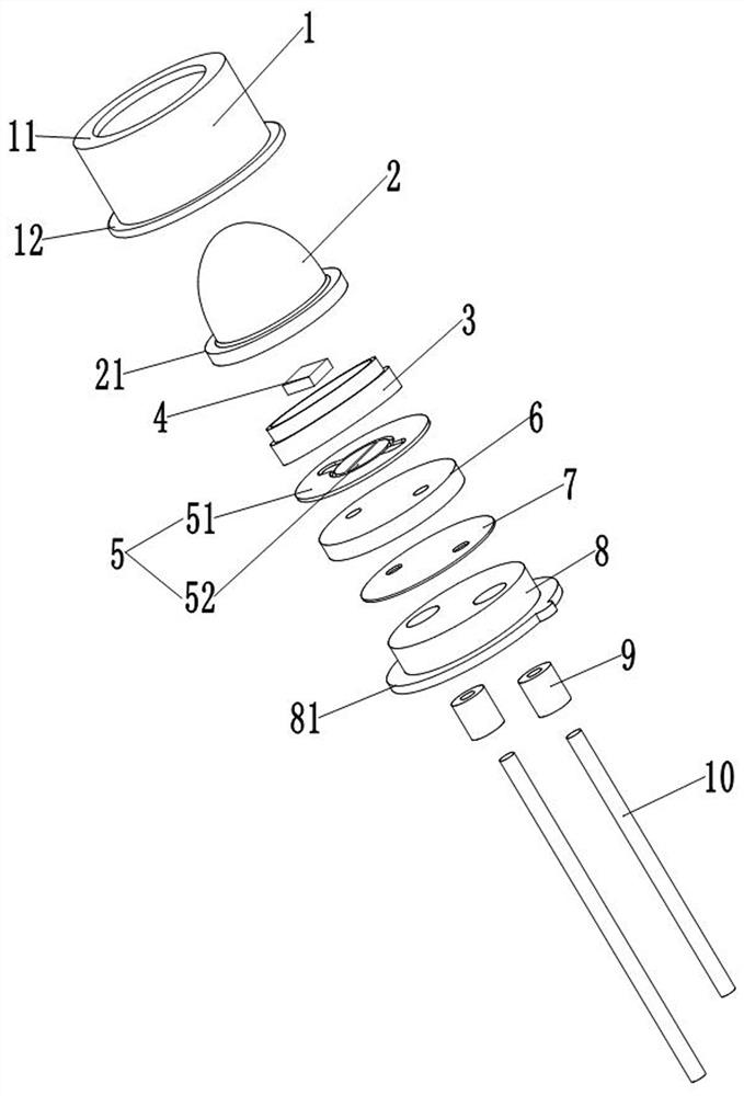
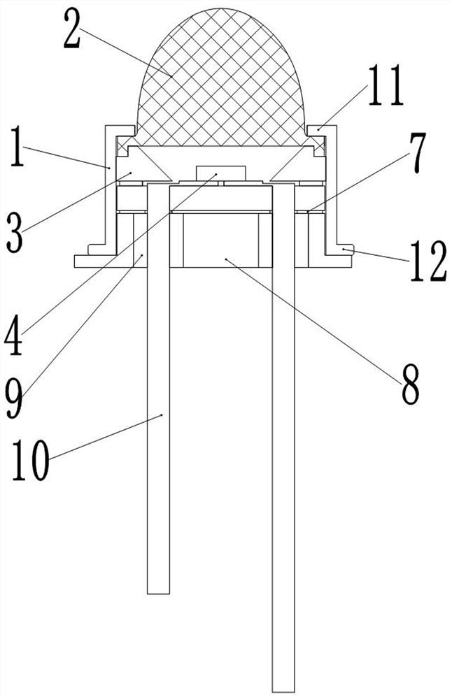
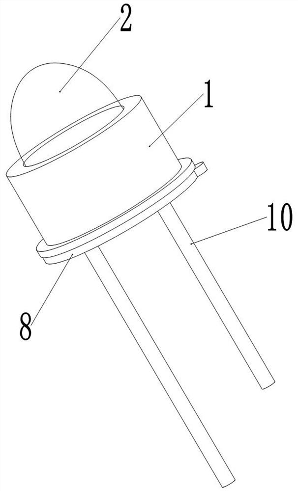

Image

  • Condensation type ultraviolet emission device packaging structure
  • Condensation type ultraviolet emission device packaging structure
  • Condensation type ultraviolet emission device packaging structure

Examples


Embodiment Construction

[0028] The technical solutions in the embodiments of the present invention will be clearly and completely described below with reference to the accompanying drawings in the embodiments of the present invention. Obviously, the described embodiments are only a part of the embodiments of the present invention, but not all of the embodiments. Based on the embodiments of the present invention, all other embodiments obtained by those of ordinary skill in the art without creative efforts shall fall within the protection scope of the present invention.

[0029] The purpose of the present invention is to provide a concentrating type ultraviolet emitting device packaging structure to solve the problems existing in the prior art. The concentrating type ultraviolet emitting device packaging structure provided by the present invention can improve the transmission distance of ultraviolet rays and the stability of the structure, Extended service life.

[0030] In order to make the above obje...


PUM


Abstract

The invention, which relates to the technical field of the semiconductor packaging structure, provides a packaging structure of a condensation type ultraviolet emission device, comprising a substrate, a light-emitting cup, an ultraviolet emission chip and a lens, the incident plane of the lens is a plane, and the light-emitting surface is a convex surface. An annular flange extending in the direction away from the lens is arranged on the peripheral face of the end, used for making contact with the light outlet cup, of the lens, a first annular boss extending towards the base is arranged on the edge, away from the lens, of the annular flange, a first annular groove is formed in the end face, provided with the light outlet, of the light outlet cup, and the first annular boss extends into the first annular groove. The inner wall of the first annular boss abuts against the side wall of the first annular groove, the bottom face of the first annular boss abuts against the bottom face of the first annular groove, the inner wall of the first annular boss is connected with the side wall of the first annular groove in an adhesive mode through an adhesive, and the bottom face of the first annular boss is connected with the bottom face of the first annular groove in an adhesive mode through an adhesive mode. According to the scheme provided by the invention, the transmission distance of ultraviolet rays and the stability of a product structure can be improved.

Description

technical field [0001] The invention relates to the technical field of semiconductor packaging structures, in particular to a packaging structure of a concentrating type ultraviolet emitting device. Background technique [0002] Deep ultraviolet light-emitting diodes (UVC LEDs) have the advantages of high reliability, long life, fast response, low power consumption, environmental protection, no pollution, and small size. They are widely used in ultraviolet light communication, sterilization and other fields. Its ultraviolet light communication has the unique advantages of flexibility, low eavesdropping, all-round, non-line-of-sight communication. Ultraviolet photons are mainly used in important communication fields such as short distance and high confidentiality. The scattering effect of deep ultraviolet photons in the atmosphere makes ultraviolet The direction of light energy transmission has changed, which has laid a communication foundation for ultraviolet light communica...

Claims


Application Information

Patent Timeline
Patent Type & Authority Applications(China)
IPC IPC(8): H01L33/60H01L33/58H01L33/48
CPCH01L33/60H01L33/58H01L33/48
Inventor 闫志超黄小辉李大超
Owner ZHIXIN SEMICON (HANGZHOU) CO LTD
Why Eureka
Try Eureka