Wireless electric energy data hybrid transmission rotary connector

A rotary connector and hybrid transmission technology, used in flexible/rotatable wire connectors, connections, circuits, etc., can solve problems such as poor reliability, discontinuous contact impedance, data loss, etc., to ensure high-power electrical energy and data stability. No loss, the effect of shortening the axial dimension

Pending Publication Date: 2022-03-01
CHINA AVIATION OPTICAL-ELECTRICAL TECH CO LTD
View PDF0 Cites 0 Cited by
  • Summary
  • Abstract
  • Description
  • Claims
  • Application Information

AI Technical Summary

Problems solved by technology

At present, traditional rotary connectors have obvious shortcomings: 1. The use scenarios of pure wireless data transmission and pure wireless power transmission are limited to a certain extent. At present, there is no wireless power data hybrid transmission rotary connector on the market
Due to the influence of the internal structure of the rotary connector, it is large in size and high in weight, which limits many usage scenarios; 3. Low data transmission rate
When the brush wire and slip ring rotate at high speed, the contact point impedance discontinuity will lead to data loss; 4. Low life
Contact friction between brush wire and slip ring, resulting in contact wear; 5. Poor reliability
The contact friction between the brush wire and the slip ring will cause contact sparks and affect the transmission reliability; 6. It cannot be rotated at high speed for transmission
When rotating at high speed, there will be continuous contact sparks in power transmission, which is extremely unsafe; when rotating at high speed for data transmission, the contact impedance is discontinuous, and high-speed signals cannot be transmitted

Method used


Image

  • Wireless electric energy data hybrid transmission rotary connector
  • Wireless electric energy data hybrid transmission rotary connector
  • Wireless electric energy data hybrid transmission rotary connector

Examples


Embodiment Construction

[0039] The technical solutions of the present invention will be further described in detail below in conjunction with the accompanying drawings and preferred embodiments.

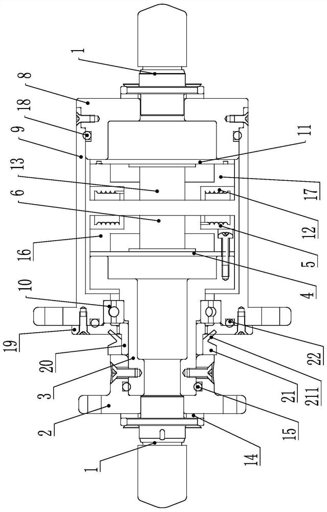
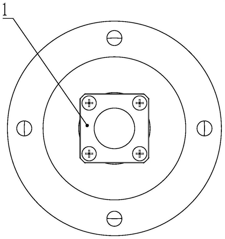
[0040] see Figure 1 to Figure 5 , a wireless power data mixed transmission rotary connector, including a rotor part and a stator part, the rotor part includes a rotor end interface connector 1, a flange 2, a rotating shaft 3, a rotor end circuit board 4, an electric energy transmitting coil 5 and a rotor The end antenna module 6 , the stator part includes a stator end interface connector 7 , a tail end cover 8 , an outer shell 9 , a bearing 10 , a stator end circuit board 11 , a power receiving coil 12 and a stator end antenna module 13 . For ease of description, it is defined that the installation position of the rotor-end interface connector is the rear end of the rotor component, and the installation position of the stator-end interface connector is the rear end of the stator component.

[0041] The ro...


PUM


Abstract

The invention relates to a wireless electric energy data hybrid transmission rotary connector, which comprises a rotor part and a stator part, and is characterized in that the rotor part comprises a rotor end interface connector, a rotating shaft, a rotor end circuit board, an electric energy transmitting coil and a rotor end antenna module; the stator component comprises a stator end interface connector, an outer shell, a bearing, a stator end circuit board, an electric energy receiving coil and a stator end antenna module; the rotor end interface connector is electrically connected with the rotor end circuit board; the stator end interface connector is electrically connected with the stator end circuit board; the front end of the outer shell is rotationally connected with the rotating shaft through a bearing; the rotor end circuit board is electrically connected with the electric energy transmitting coil, the stator end circuit board is electrically connected with the electric energy receiving coil, and the electric energy receiving coil and the transmitting coil are oppositely arranged so as to realize wireless electric energy transmission; and the stator end antenna module and the rotor end antenna module are oppositely arranged so as to realize bidirectional wireless data transmission. The service life of the connector can be prolonged while wireless mixed transmission of electric energy data is realized.

Description

technical field [0001] The invention belongs to the technical field of rotary connectors, in particular to a rotary connector for mixed transmission of wireless power and data. Background technique [0002] With the advent of the 5G era, the existing rotary connectors can no longer keep up with the growing demand. Modern industrial scenarios require faster and more reliable power and data transmission between rotating parts. As this demand grows, so do the bandwidth, crosstalk and EMI performance requirements of data interfaces used in rotary joints. Meeting these requirements is crucial to guarantee real-time operation, continuous uptime and maximum efficiency of the corresponding industrial equipment. In the military, as the equipment is updated, the rotation speed of the rotary connector is required to be higher and higher, the life is longer, and the transmission rate is gradually increased to Gbps. At present, traditional rotary connectors have obvious shortcomings: 1...

Claims


Application Information

Patent Timeline
Patent Type & Authority Applications(China)
IPC IPC(8): H01R35/00H02J50/00H02J50/10
CPCH01R35/00H02J50/005H02J50/10
Inventor 张磊周鹏举张冬波郭建设
Owner CHINA AVIATION OPTICAL-ELECTRICAL TECH CO LTD
Why Eureka
Try Eureka