Oil cooling structure of driving motor and processing method thereof

A driving motor and oil cooling technology, applied in the manufacture of motor generators, magnetic circuit shape/style/structure, electromechanical devices, etc., can solve the problems of high processing cost, limited motor thermal load, limited motor volume, etc., to achieve Reduce the influence of tolerances, avoid misalignment of oil passages, and improve adaptability

Pending Publication Date: 2022-03-01
LEADRIVE TECH (SHANGHAI) CO LTD
View PDF4 Cites 0 Cited by
  • Summary
  • Abstract
  • Description
  • Claims
  • Application Information

AI Technical Summary

Problems solved by technology

[0003] At present, during the actual operation of the motor, when the motor is at low speed and high torque, the stator and rotor of the motor will emit a lot of heat. Circulating flow, and then realize the cooling effect of the motor. In this cooling method, the motor stator winding (coil) and the rotor cannot be directly cooled, and the main heat source of the motor cannot be effectively cooled. Therefore, the thermal load of the motor is limited, which leads to The size of the motor is limited
[0004] In the prior art, in order to improve the cooling efficiency of the motor, an oil-cooled cooling method has appeared. Since the cooling oil is not conductive, it can directly contact the heat sources of the motor, and the heat sources of the motor can be effectively cooled. Under the requirement, compared with the traditional water-cooled motor, the heat load of the oil-cooled motor is increased, the volume of the motor can be reduced, and the power density can be further improved. The cooling oil can lubricate and cool the motor bearing at the same time, and the life of the motor is also improved, but the structure of the oil circuit is complicated. , The processing technology is cumbersome, the oil circuit structure mostly adopts screw fastening, welding and other processing technology, the structure of each component is complicated, and the processing cost is high.

Method used


Image

  • Oil cooling structure of driving motor and processing method thereof
  • Oil cooling structure of driving motor and processing method thereof
  • Oil cooling structure of driving motor and processing method thereof

Examples


Embodiment 1

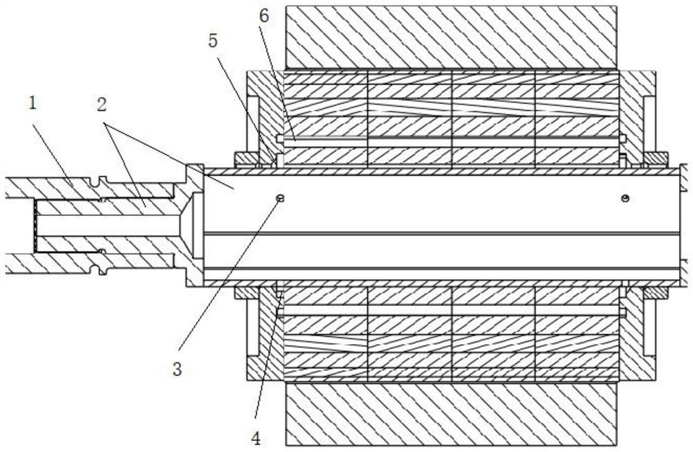
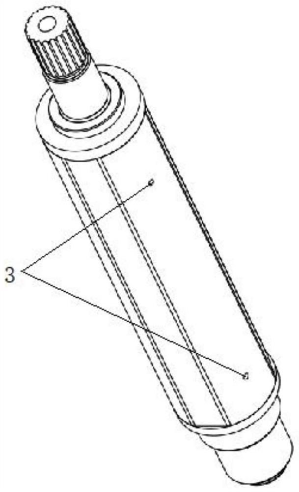
[0062] Embodiment one, see appendix Figure 1-3 The outer surface of the rotor shaft 2 is provided with a first spline, the inner surface of the reducer shaft 1 is provided with a second spline matching the first spline, and the reducer shaft 1 is sleeved on the second part of the rotor shaft 2 In addition, because it is installed outside, it does not extend into the first part of the rotor shaft 2, so it is staggered with the axial position of the balance plate, and the oil guide hole 3 will be directly opened on the inner wall of the rotor shaft 2, and the second oil hole of the balance plate will be directly opened. Corresponds to the location of Road 7.

[0063] See attached Figure 4 , the arrow part is the flow direction of the cooling oil. After the external cooling oil enters the first oil passage in the rotor through the oil inlet passage of the reducer, under the rotation of the rotor, it is dispersed to the inner wall of the rotor shaft 2 due to the centrifugal for...

Embodiment 2

[0065] Embodiment two, see appendix Figure 5-7The inner surface of the rotor shaft 2 is provided with a first spline, the outer surface of the reducer shaft 1 is provided with a second spline matching the first spline, and the reducer shaft 1 is sleeved on the first part of the rotor shaft 2 In the first oil passage, in order to further reduce the axial size of the reducer shaft 1 and the rotor shaft 2, the reducer shaft 1 will extend into the first part of the rotor shaft 2, and at this time it will coincide with the axial position of the balance plate, The oil guide hole 3 corresponding to the radial position of the second oil passage 7 (or the first ring groove 4) of the balance disc on the inner surface of the rotor will be blocked, so that the oil cannot circulate, so in this embodiment, the rotor shaft 2 The first spline on the reducer shaft 1 and the second spline on the reducer shaft 1 are disconnected at the same position, so that when the two splines cooperate, a ga...

Embodiment 3

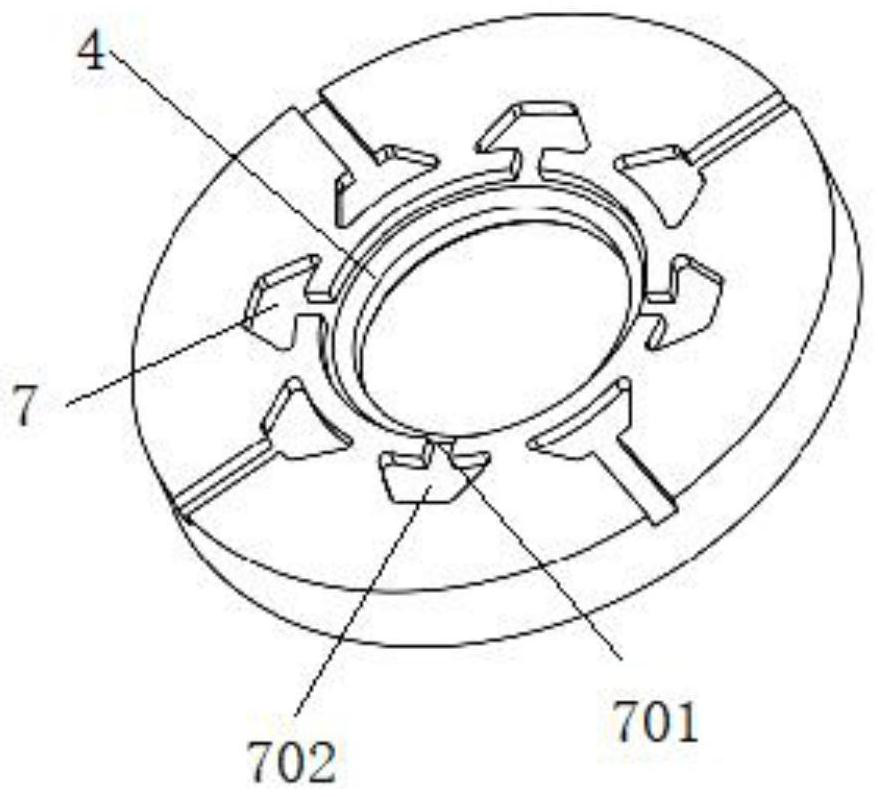
[0070] Embodiment three, see appendix Figure 9-11 , the same as the second embodiment, the reducer shaft 1 is sleeved in the first oil passage of the first part of the rotor shaft 2, and extends into the first part of the rotor shaft 2, and coincides with the axial position of the balance plate, blocking the The oil guide hole 3 on the inner surface of the rotor corresponding to the radial position of the second oil channel 7 (or the first ring groove 4 ) of the balance plate prevents oil from circulating.

[0071] The difference from Embodiment 2 is that in this embodiment, the second oil guide hole 302 on the wall surface of the first oil passage includes a first sub-path 30201 and a second sub-path 30202 that intersect, and the first sub-path 30201 has a diameter of The second sub-channel 30202 is axially arranged on the second part of the rotor shaft 2 and communicates with the second oil passage 7 and the rotor shaft 2 outer walls. One end of the first sub-channel 3020...


PUM


Abstract

According to the oil cooling structure of the driving motor and the processing method of the oil cooling structure, the oil guide hole in the rotor shaft and the second oil channel in the balance disc form a cooling path for cooling oil to flow from the rotor shaft to the rotor core, so that the rotor shaft can be cooled, and the rotor core can also be cooled; the tolerance influence is reduced, and the adaptability of the shaft is improved; according to different inner and outer spline arrangements of a rotor shaft and a speed reducer shaft, the space of the overlapped part of the shaft and the splines is fully utilized, and the overall axial size is controlled; compared with a welding shaft capable of carrying out clearance design on splines, the rigid shaft cannot carry out clearance design on the splines, so that the speed reducer shaft and the rotor shaft are provided with the grooves in the same positions and are synchronously provided with the holes, and communication of the first oil channel and the first annular groove is achieved; according to the method, the assembly process and requirements of special light-weight shafts such as rigid shafts and welding shafts are fully considered.

Description

technical field [0001] The invention relates to the technical field of driving motors, in particular to an oil cooling structure of a driving motor and a processing method thereof. Background technique [0002] The motor refers to an electromagnetic device that realizes the conversion or transmission of electric energy according to the law of electromagnetic induction. It is mainly determined by the left-hand rule through the direction of the force on the conductor. This pair of electromagnetic forces forms a torque acting on the armature. This torque is called electromagnetic torque in the rotating electrical machine. The direction of the torque is counterclockwise, trying to make the armature rotate counterclockwise. If this electromagnetic torque can overcome the resistance torque on the armature (such as the resistance torque caused by friction and other load torques), the armature can rotate counterclockwise. [0003] At present, during the actual operation of the moto...

Claims


Application Information

Patent Timeline
IPC IPC(8): H02K9/19H02K1/32H02K7/00H02K15/00H02K15/02
CPCH02K9/19H02K1/32H02K7/003H02K15/00H02K15/02Y02T10/64
Inventor 沈捷庄浩钦陈晓滨
Owner LEADRIVE TECH (SHANGHAI) CO LTD
Why Eureka
Try Eureka