Two-degree-of-freedom self-decoupling large-rigidity large-stroke piezoelectric quick servo tool rest

A technology of servo tool post and degree of freedom, which is applied in the direction of piezoelectric effect/electrostrictive or magnetostrictive motors, electrical components, generators/motors, etc., can solve the problems of decreased accuracy, increase the scope of processing, etc., and achieve The effect of increasing the applicable range of processing, improving the overall rigidity and working stability

Pending Publication Date: 2022-03-01
WENZHOU UNIVERSITY
View PDF0 Cites 2 Cited by
  • Summary
  • Abstract
  • Description
  • Claims
  • Application Information

AI Technical Summary

Problems solved by technology

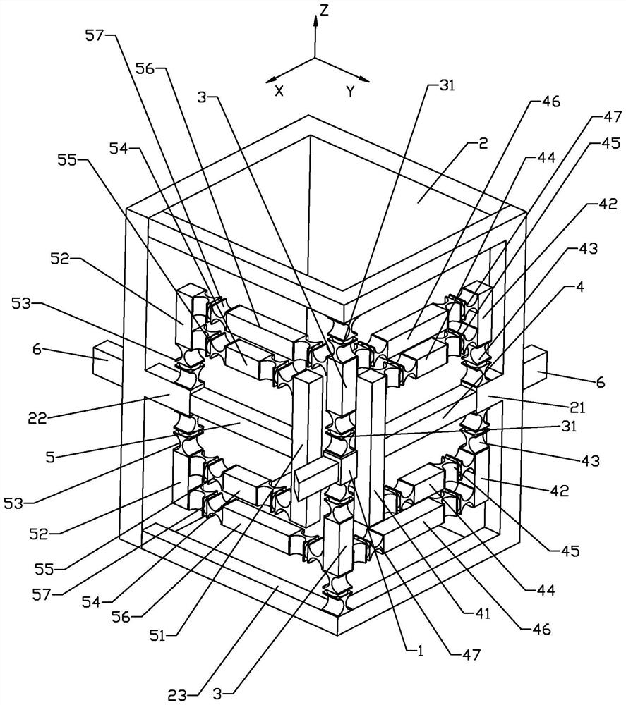
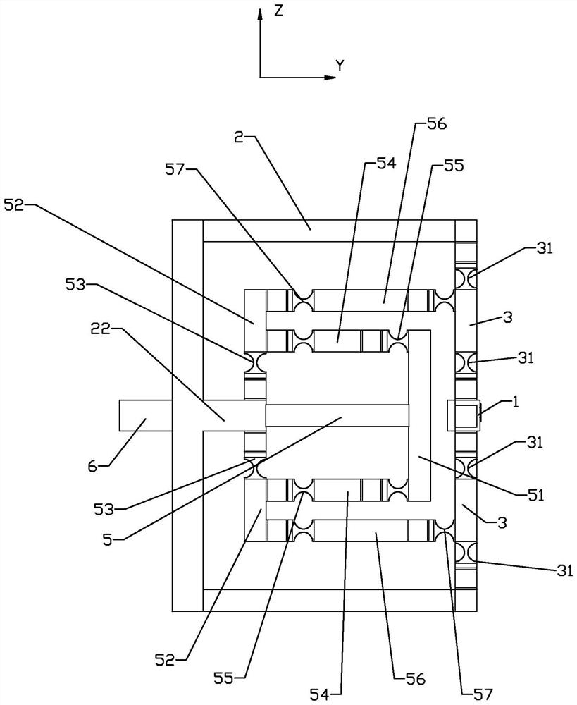
[0006] By adopting the above-mentioned technical scheme, the secondary lever amplifying mechanism integrated in the servo tool post is composed of multiple amplifying hinge groups and multiple vertical bars and horizontal bars. The two piezoelectric ceramic drivers will The driving stroke is transmitted to the tool control vertical bar of the tool assembly to meet the processing requirements of the dual-degree-of-freedom servo tool holder based on the piezoelectric ceramic driver. During the transmission process, the arrangement of the enlarged hinge group can effectively connect the two piezoelectric ceramic drivers Decoupling the driving effect of the tool to solve the problem of decreased precision caused by the coupling. At the same time, the two secondary lever amplification mechanisms form a three-dimensional support structure with horizontal and vertical cooperation, which constitutes a stable support for the tool in all directions and effectively improves the stability of the device. The overall rigidity and working stability. In addition, the driving stroke output by the two piezoelectric ceramic drivers is amplified, so as to overcome the physical characteristics of the piezoelectric ceramic driver, meet the processing needs of long strokes, and increase the scope of processing. In addition, adjust the tool The tool control vertical bar of the position of the assembly is also assembled with the base through the installation of the hinge group, forming an assembly structure for the stable movement of the tool assembly

Method used


Image

  • Two-degree-of-freedom self-decoupling large-rigidity large-stroke piezoelectric quick servo tool rest
  • Two-degree-of-freedom self-decoupling large-rigidity large-stroke piezoelectric quick servo tool rest
  • Two-degree-of-freedom self-decoupling large-rigidity large-stroke piezoelectric quick servo tool rest

Examples


Embodiment Construction

[0017] The technical solutions of the present invention will be clearly and completely described below in conjunction with the accompanying drawings. Apparently, the described embodiments are some of the embodiments of the present invention, but not all of them. Based on the embodiments of the present invention, all other embodiments obtained by persons of ordinary skill in the art without making creative efforts belong to the protection scope of the present invention.

[0018] In the description of the present invention, it should be noted that the terms "center", "upper", "lower", "left", "right", "vertical", "horizontal", "inner", "outer" etc. The indicated orientation or positional relationship is based on the orientation or positional relationship shown in the drawings, and is only for the convenience of describing the present invention and simplifying the description, rather than indicating or implying that the referred device or element must have a specific orientation, ...


PUM


Abstract

The invention relates to a two-degree-of-freedom self-decoupling large-rigidity large-stroke piezoelectric rapid servo tool rest which comprises a tool, a base and a piezoelectric ceramic driver. An installation hinge set composed of a transverse deformation flexible hinge and a longitudinal deformation flexible hinge is arranged between the other end, opposite to the cutter, of the cutter adjusting and controlling vertical rod and the base, and the two piezoelectric ceramic drivers are located on the two sides of the cutter correspondingly. The piezoelectric ceramic drivers comprise a first piezoelectric ceramic driver for outputting longitudinal driving force and a second piezoelectric ceramic driver for outputting transverse driving force, and the two piezoelectric ceramic drivers are respectively provided with a two-stage lever amplification mechanism with a decoupling function. By the adoption of the scheme, the two-degree-of-freedom self-decoupling large-rigidity large-stroke piezoelectric rapid servo tool rest is high in precision, the stroke is enlarged, and the machining stability is improved.

Description

technical field [0001] The invention relates to the field of ultra-precision optical processing, in particular to a dual-degree-of-freedom self-decoupling, large-rigidity, and large-stroke piezoelectric fast servo tool holder. Background technique [0002] Complex optical curved surface parts can simplify the optical system structure, improve optical utilization, provide more flexible system layout, and have a higher degree of design freedom. When applied in the optical system, it can well correct various aberrations and improve the imaging quality of the instrument. Improve the ability of instrument identification. Therefore, with the development of the precision optics industry, parts with complex optical surfaces have been used in optical fiber communication, aerospace, national defense, life science and medical treatment, semiconductor lithography and testing equipment, unmanned driving, biometrics, AR / VR testing Equipment and other fields have been widely used. For th...

Claims


Application Information

Patent Timeline
Patent Type & Authority Applications(China)
IPC IPC(8): H02N2/02H02N2/04B28D1/00B28D7/00
CPCH02N2/028H02N2/043B28D1/00B28D7/00
Inventor 邱辉夏琨罗祥黄磊王小龙李国平
Owner WENZHOU UNIVERSITY
Why Eureka
Try Eureka