Wrist scaphoid bone replacement prosthesis

A part of the navicular bone technology, applied in the field of wrist partial navicular bone replacement prosthesis, can solve the problems of limited curative effect, cumbersome and other problems, to simplify the operation and rehabilitation process, improve the movement and function of the wrist joint, restore or the movement and function of the wrist joint Effect

Pending Publication Date: 2022-03-04
中国人民解放军联勤保障部队第九二〇医院
View PDF0 Cites 1 Cited by
  • Summary
  • Abstract
  • Description
  • Claims
  • Application Information

AI Technical Summary

Problems solved by technology

At present, for advanced scaphoid nonunion, proximal necrosis, progressive wrist arthritis, etc., traditional methods are cumbersome and have limited efficacy

Method used


Image

  • Wrist scaphoid bone replacement prosthesis
  • Wrist scaphoid bone replacement prosthesis
  • Wrist scaphoid bone replacement prosthesis

Examples


Embodiment 1

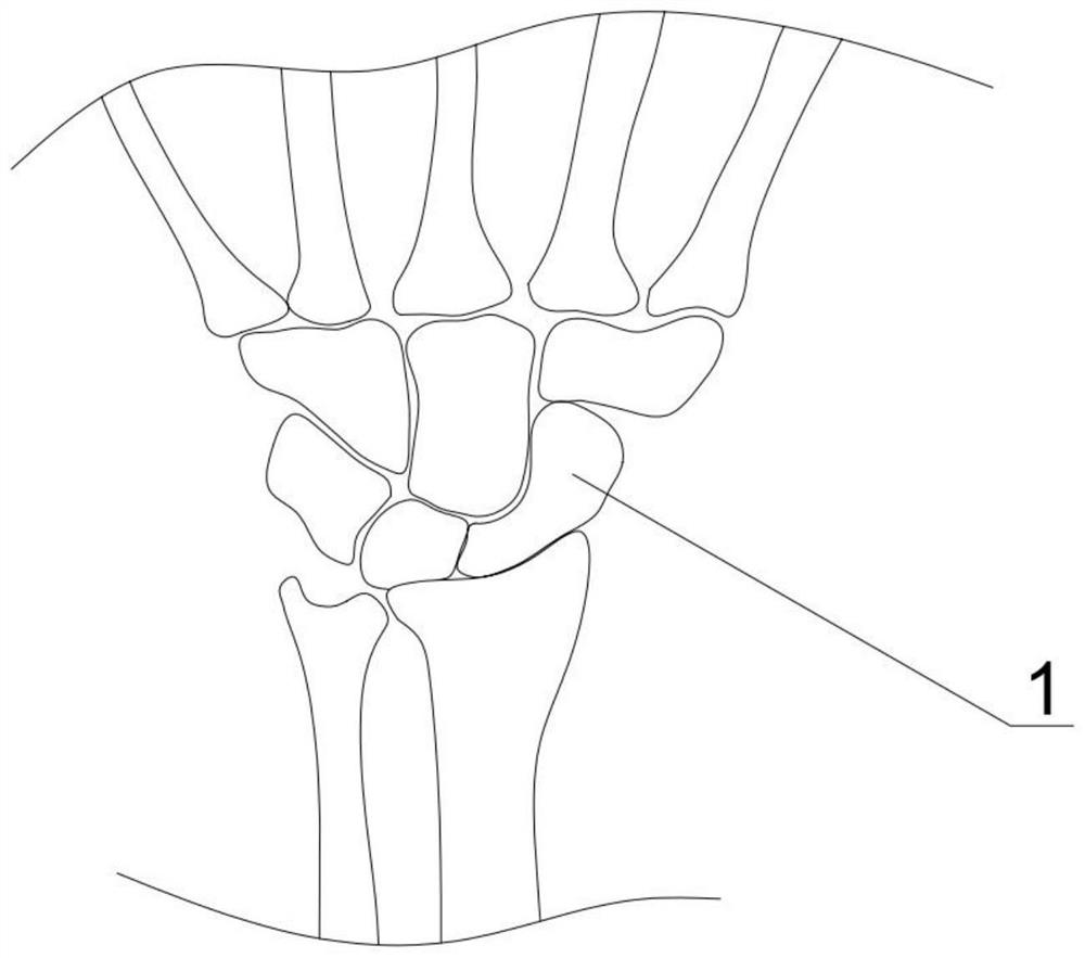
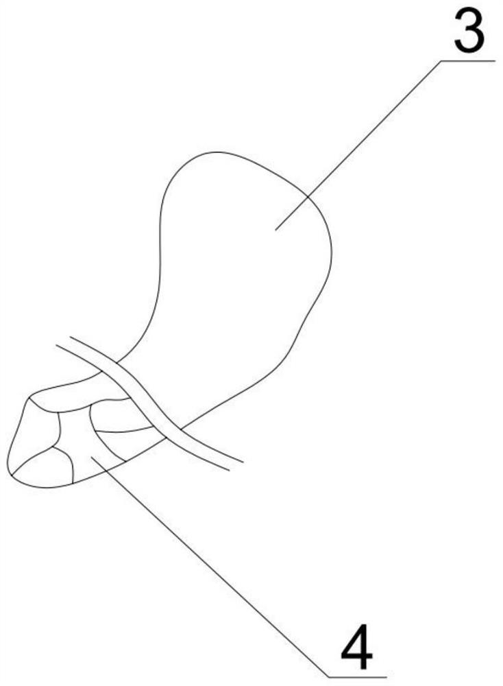
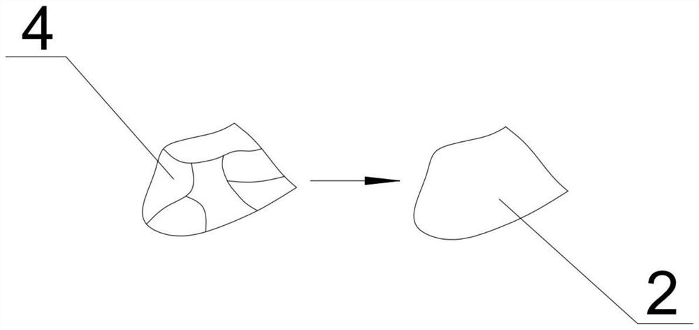
[0034] refer to Figure 1 to Figure 6 As shown, a wrist partial scaphoid replacement prosthesis is characterized in that it includes: a replacement part of the scaphoid 4, a residual healthy scaphoid 3, an anti-rotation compression screw 5, and a transplanted prosthesis 2;

[0035] The replacement part of the scaphoid 4 is a part of the carpal scaphoid, the transplanted prosthesis 2 is fixedly connected to the remaining healthy navicular bone 3, one end of the anti-rotation compression screw 5 is fixedly connected to the transplanted prosthesis 2, and the other end is fixedly connected to the grafted prosthesis 2. On the remaining healthy scaphoid 3; the end face of the connecting head between the remaining healthy scaphoid 3 and the transplanted prosthesis 2 is concave; the structural shape of the transplanted prosthesis 2 is completely consistent with the structural shape of the replacement part of the scaphoid 4, which is exactly the same as the transplanted prosthesis 2. O...

Embodiment 2

[0047] Yet another embodiment of the present invention is a method for making a wrist partial scaphoid replacement prosthesis, which is a partial wrist scaphoid replacement prosthesis, which is characterized in that it includes: a replacement partial scaphoid 4, a residual healthy scaphoid 3, an anti-scaphoid Rotate compression screw 5, transplant prosthesis 2; The replacement part navicular bone 4 is a part of the carpal navicular bone, the transplant prosthesis 2 is fixedly connected with the remaining healthy navicular bone 3, and one end of the anti-rotation compression screw 5 is fixedly connected to the transplanted On the prosthesis 2, the other end is fixedly connected to the residual healthy navicular bone 3;

[0048] Its production method is as follows:

[0049] 1. A high-resolution CT scan of the patient's bilateral wrist joints was performed, and DICOM format data of the bilateral wrist joints were obtained.

[0050] 2. Transfer the data in DICOM format to MIMICS so...


PUM


Abstract

The invention discloses a wrist part scaphoid bone replacement prosthesis, which is characterized by comprising a replacement part scaphoid bone, a residual healthy scaphoid bone, an anti-rotation forcing screw and a transplantation prosthesis, the replacement part navicular bone is a part of the carpal navicular bone, the transplantation prosthesis is fixedly connected with the residual healthy navicular bone, one end of the anti-rotation forcing screw is fixedly connected to the transplantation prosthesis, and the other end of the anti-rotation forcing screw is fixedly connected to the residual healthy navicular bone; according to the prosthesis, a three-dimensional scaphoid model of a patient is constructed through three-dimensional CT scanning of the scaphoid of the carpal bone at the intact position of the patient, and a three-dimensional model of a scaphoid replacement part is obtained by mirroring the three-dimensional model. Therefore, the scaphoid fracture healing process is directly simplified, the conditions of slow healing, non-healing and ischemic death of the two scaphoids after scaphoid fracture are avoided, the scaphoid fracture rehabilitation speed of the carpal bone is increased, the inconvenience of wrist movement caused by scaphoid fracture healing disorder in the later period is avoided, the later-period hidden danger is eliminated, and the postoperative rehabilitation quality of a patient is guaranteed.

Description

technical field [0001] The invention belongs to the field of medical technology, and in particular relates to a prosthesis for replacing the scaphoid of the wrist. Background technique [0002] The navicular is a small bone in the wrist joint. The navicular bone is close to the radial side of the row, and its shape is like a boat, hence its name. Its appearance is irregular, and its back is narrow and long, forming joints with the radius, capitate, trapezium, and trapezium. Navicular fractures are the most common fractures of the wrist. After scaphoid fractures, approximately 5-15% develop scaphoid nonunion. Its main manifestations are wrist joint pain, limited wrist joint movement, and decreased grip strength, which seriously affect daily life and work. Scaphoid nonunion changes the biomechanical relationship between the radiocarpal joint and the middle wrist joint, and does not match the activities of the surrounding joints, resulting in abnormal wear, kyphosis, dorsal...

Claims


Application Information

Patent Timeline
Patent Type & Authority Applications(China)
IPC IPC(8): A61F2/28
CPCA61F2/28A61F2/30942A61F2002/30948
Inventor 何晓清石岩杨曦徐月仙
Owner 中国人民解放军联勤保障部队第九二〇医院
Why Eureka
Try Eureka