
Cutting machine tool follow-up dust removal control system, method and device and storage medium

A cutting machine tool and control system technology, applied in the direction of manufacturing tools, metal processing machinery parts, metal processing equipment, etc., can solve the problems of poor dust collection effect, high energy consumption, and constant changes, so as to improve the cutting environment , Improve the effect of air cleanliness

Active Publication Date: 2022-03-04
YITELI SHANGHAI SCI TECH CO LTD
View PDF8 Cites 0 Cited by
  • Summary
  • Abstract
  • Description
  • Claims
  • Application Information

AI Technical Summary

Problems solved by technology

[0003] In related technologies, dust collection systems are often used to remove debris or floating objects generated during the cutting process. However, dust collection systems are mostly adapted to cutting heads for fixed-point machining. During the movement of the cutting head, its processing position will change continuously, and the corresponding dust collection system can only choose to expand the volume of the dust collection cover to cover the processing space of the cutting head
[0004] However, the above-mentioned large-scale vacuuming method, on the one hand, has a poor vacuuming effect, and some small particles cannot be sucked out; on the other hand, due to the large volume of the vacuum hood, the corresponding energy consumption is relatively large

Method used


Image

  • Cutting machine tool follow-up dust removal control system, method and device and storage medium
  • Cutting machine tool follow-up dust removal control system, method and device and storage medium
  • Cutting machine tool follow-up dust removal control system, method and device and storage medium

Examples


Embodiment Construction

[0057] The following will clearly and completely describe the technical solutions in the embodiments of the present invention with reference to the accompanying drawings in the embodiments of the present invention. Obviously, the described embodiments are only some, not all, embodiments of the present invention.

[0058]It should be noted that when an element is referred to as being “fixed” to another element, it can be directly on the other element or there can also be an intervening element. When an element is referred to as being "connected to" another element, it can be directly connected to the other element or intervening elements may also be present. The terms "vertical," "horizontal," "left," "right," and similar expressions are used herein for purposes of illustration only and are not intended to represent the only embodiments.

[0059] Unless otherwise defined, all technical and scientific terms used herein have the same meaning as commonly understood by one of ordin...


PUM


Abstract

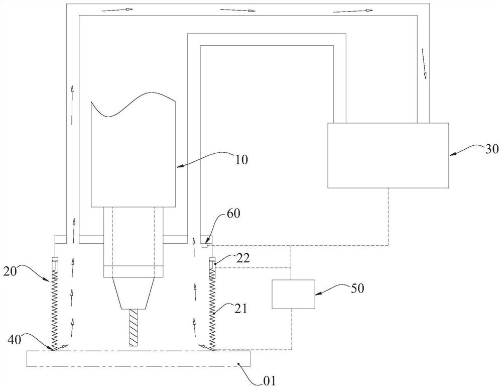
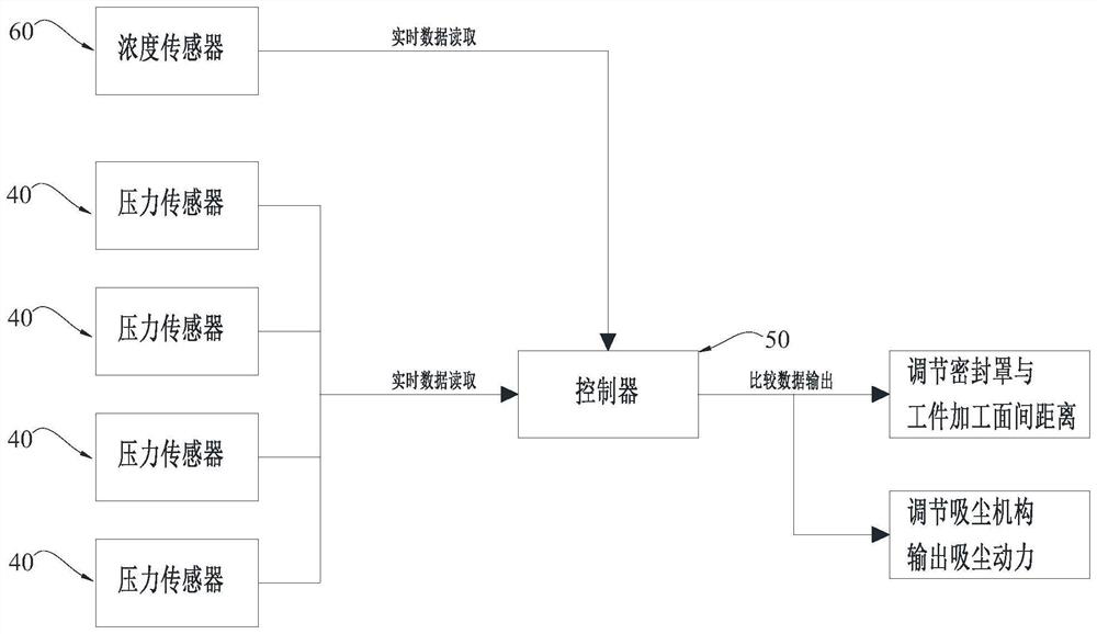
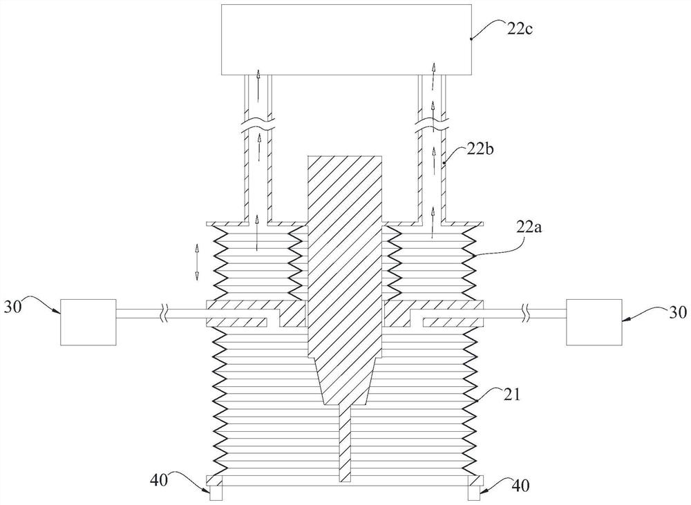
The invention relates to the technical field of numerical control machine tools, in particular to a cutting machine tool follow-up dust removal control system, method and device and a storage medium. The dust removal cover mechanism covers the cutting main shaft; the dust collection mechanism is communicated with the dust removal cover mechanism through a pipeline; the pressure sensors are uniformly arranged at the bottom of the dust hood mechanism at intervals and used for detecting pressure between the bottom of the dust hood mechanism and the workpiece; the controller is electrically connected with the pressure sensor and used for receiving data of the pressure sensor; wherein the dust removal cover mechanism comprises a sealing cover and a vertical driving assembly, the vertical driving assembly is connected with the sealing cover, the vertical driving assembly is electrically connected with the controller, and when a numerical value received by the controller is larger than the upper limit of a threshold value, the vertical driving assembly drives the sealing cover to be lifted; when the numerical value received by the controller is smaller than the lower limit of the threshold value, the vertical driving mechanism drives the sealing cover to press downwards so as to ensure that the pressure between the bottom of the sealing cover and the workpiece is within the set distance range.

Description

technical field [0001] The invention relates to the technical field of numerical control machine tools, in particular to a control system, method, device and storage medium for follow-up dust removal of cutting machine tools. Background technique [0002] During the processing of workpieces, cutting machine tools will produce cutting debris and floating particles, which will have a great impact on the environment of the workshop near the machine tool. Even some special materials will produce cutting floating objects that will damage the operator or equipment during the processing process. . [0003] In related technologies, dust collection systems are often used to remove debris or floating objects generated during the cutting process. However, dust collection systems are mostly adapted to cutting heads for fixed-point machining. During the movement of the cutting head, its processing position will change continuously, and the corresponding dust collection system can only c...

Claims


Application Information

Patent Timeline
Patent Type & Authority Applications(China)
IPC IPC(8): B23Q11/00B23Q11/08B23Q17/00
CPCB23Q11/00B23Q11/08B23Q17/00Y02P70/10
Inventor 刘士孔裴俊朋刘星明孟宪哲程来利
Owner YITELI SHANGHAI SCI TECH CO LTD
Learn More