Special fixture for slag stopping cone for manipulator

A special fixture and manipulator technology, which is applied in the direction of manipulators, chucks, manufacturing tools, etc., can solve problems such as high labor intensity, labor occupation, and potential safety hazards, and achieve the effects of improving production efficiency, accurate palletizing positions, and reducing maintenance costs

Pending Publication Date: 2022-03-04
莱芜钢铁双山陶土福利加工有限公司
View PDF0 Cites 0 Cited by
  • Summary
  • Abstract
  • Description
  • Claims
  • Application Information

AI Technical Summary

Problems solved by technology

[0002] During the tapping process of the converter, a large amount of liquid slag flows into the ladle simultaneously with the molten steel, and the liquid slag is also injected into the billet during the ingot casting process, which seriously affects the quality of the steel billet. Therefore, in order to improve the quality of the billet, the steelmaking plant , to remove the inclusions in the billet, before the termination of the converter tapping, adopt the slag-stopping cone input device to insert the slag-stopping cone into the tapping hole, and use the characteristics of the specific gravity of the slag-stopping cone, which is lighter than molten steel and heavier than molten slag, to make the slag-stopping The cone floats between the molten steel and the slag at the taphole to block the slag and prevent the slag in the furnace from flowing into the ladle. The slag blocking cone is large in size, heavy in weight, and has a conical shape. At present, After the slag-stopping cone is pressed, it is mainly carried by hand, which has the disadvantages of labor force and high labor intensity. Some of the slag-stopping cones are grabbed by manipulators, and fixed fixtures are used for slag-stopping cones of different sizes, which is not reliable. If the slag-stopping cone is tightly held tightly, it is easy to fall off during the grabbing process and damage the product. There are also certain safety hazards, and there is no special fixture for the slag-stopping cone. Easy to use, not easy to transfer and stack the slag stop cone

Method used


Image

  • Special fixture for slag stopping cone for manipulator
  • Special fixture for slag stopping cone for manipulator
  • Special fixture for slag stopping cone for manipulator

Examples


Embodiment 1

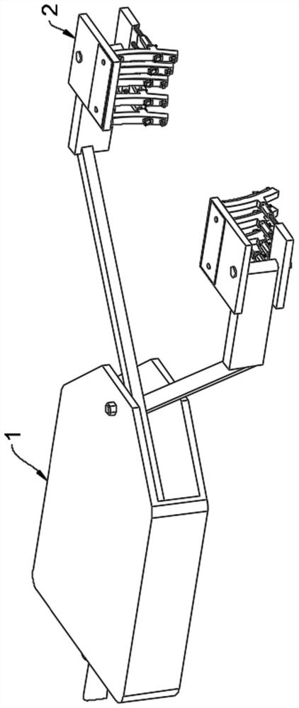
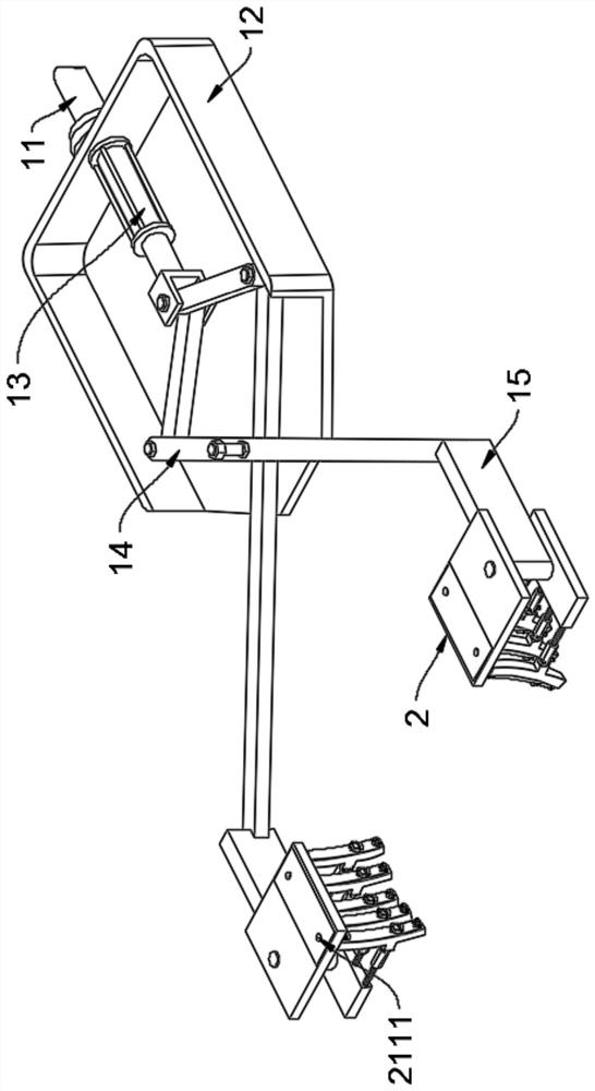
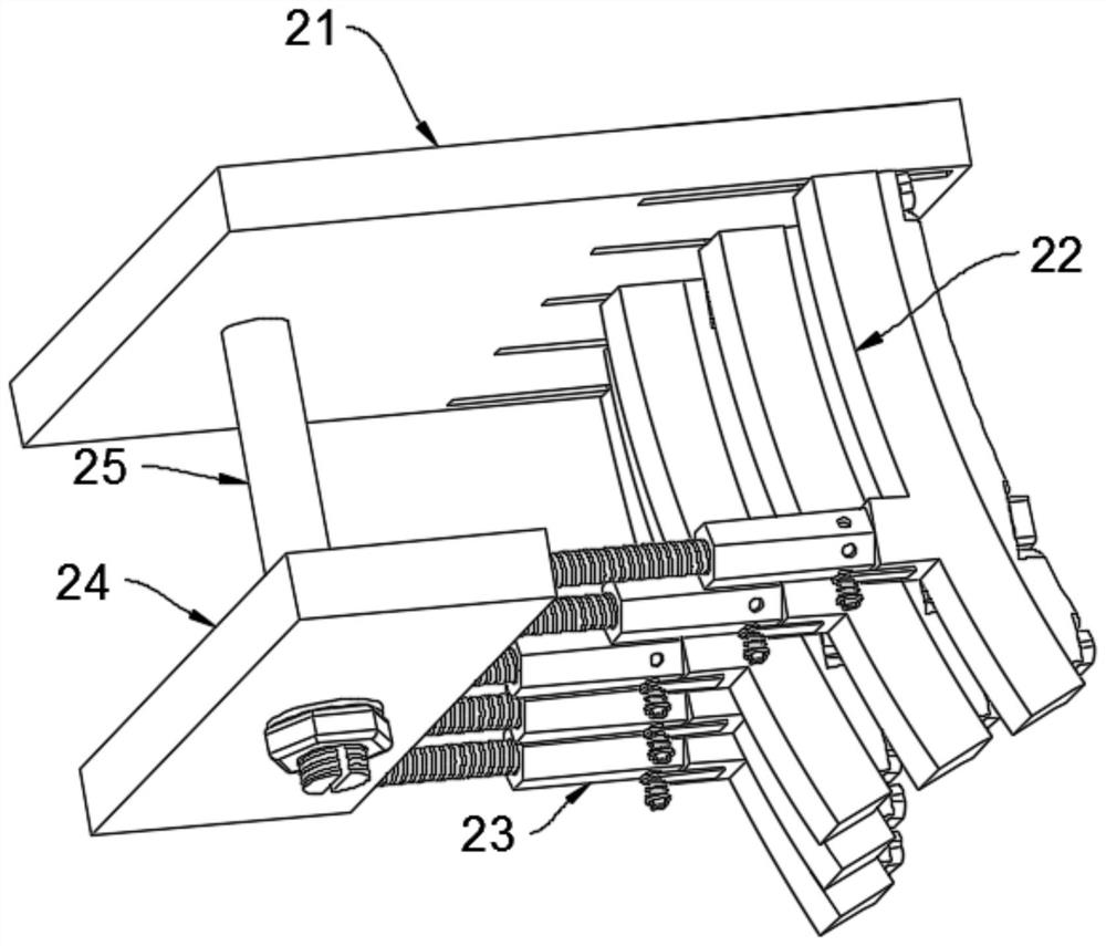
[0028] see Figure 1-9 As shown, a special clamp for slag-stopping cones for a manipulator includes a manipulator 1, and one end of the manipulator 1 is sleeved with a clamp assembly 2, and the clamp assembly 2 consists of a top plate assembly 21, a clip bar assembly 22, a connecting assembly 23, a bottom plate assembly 24 and The pin shaft assembly 25 is composed, and the clip bar assembly 22 is evenly slid and clamped on the lower surface side of the top plate assembly 21. The clip bar assemblies 22 form an arc structure, and the clip bar assembly 22 and the bottom plate assembly 24 pass through the connecting assembly 23 are fixedly connected, and the pin assembly 25 is inserted between the top plate assembly 21 and the bottom plate assembly 24, and the output end of the manipulator 1 is sleeved on the pin assembly 25, the clamp assembly 2 is two groups, and the clamp assembly 2 In a relative structure, the manipulator 1 includes a rotating shaft 11, and the rotating shaft ...

Embodiment 2

[0031] see Figure 1-9 As shown, a special clamp for slag-stopping cones for a manipulator includes a manipulator 1, and one end of the manipulator 1 is sleeved with a clamp assembly 2, and the clamp assembly 2 consists of a top plate assembly 21, a clip bar assembly 22, a connecting assembly 23, a bottom plate assembly 24 and The pin shaft assembly 25 is composed, and the clip bar assembly 22 is evenly slid and clamped on the lower surface side of the top plate assembly 21. The clip bar assemblies 22 form an arc structure, and the clip bar assembly 22 and the bottom plate assembly 24 pass through the connecting assembly 23 are fixedly connected, and the pin assembly 25 is inserted between the top plate assembly 21 and the bottom plate assembly 24, and the output end of the manipulator 1 is sleeved on the pin assembly 25, the clamp assembly 2 is two groups, and the clamp assembly 2 In a relative structure, the manipulator 1 includes a rotating shaft 11, and the rotating shaft ...

Embodiment 3

[0034] see Figure 1-9 As shown, a special clamp for slag-stopping cones for a manipulator includes a manipulator 1, and one end of the manipulator 1 is sleeved with a clamp assembly 2, and the clamp assembly 2 consists of a top plate assembly 21, a clip bar assembly 22, a connecting assembly 23, a bottom plate assembly 24 and The pin shaft assembly 25 is composed, and the clip bar assembly 22 is evenly slid and clamped on the lower surface side of the top plate assembly 21. The clip bar assemblies 22 form an arc structure, and the clip bar assembly 22 and the bottom plate assembly 24 pass through the connecting assembly 23 are fixedly connected, and the pin assembly 25 is inserted between the top plate assembly 21 and the bottom plate assembly 24, and the output end of the manipulator 1 is sleeved on the pin assembly 25, the clamp assembly 2 is two groups, and the clamp assembly 2 In a relative structure, the manipulator 1 includes a rotating shaft 11, and the rotating shaft ...


PUM


Abstract

The invention discloses a special fixture for a slag stopping cone for a manipulator, and belongs to the technical field of slag stopping cone clamping devices.The special fixture comprises the manipulator, one end of the manipulator is sleeved with a fixture assembly, and the fixture assembly is composed of a top plate assembly, a clamping strip assembly, a connecting assembly, a bottom plate assembly and a pin shaft assembly and is convenient to assemble; according to the device, part of components can be replaced conveniently, the maintenance cost is reduced, through a lead screw and a threaded pipe, the position of an arc-shaped strip can be adjusted conveniently, the radian formed between arc-shaped plates can be adjusted conveniently, slag stopping cones of different specifications can be used conveniently, through an air bag strip and an upper fixing plate, the situation that the slag stopping cones fall off during clamping and after overturning is avoided, and the service life of the slag stopping cones is prolonged. And through the limiting disc, during use, rotation of the pin rod is limited, looseness between the clamp assembly and the mechanical arm is avoided, the stability during use is improved, then the stacking position of the slag stopping cone is more accurate, and the production efficiency is effectively improved.

Description

technical field [0001] The invention relates to a fixture, in particular to a special fixture for a slag-stopping cone for a manipulator, and belongs to the technical field of slag-stopping cone clamping devices. Background technique [0002] During the tapping process of the converter, a large amount of liquid slag flows into the ladle simultaneously with the molten steel, and the liquid slag is also injected into the billet during the ingot casting process, which seriously affects the quality of the steel billet. Therefore, in order to improve the quality of the billet, the steelmaking plant , to remove the inclusions in the billet, before the termination of the converter tapping, adopt the slag-stopping cone input device to insert the slag-stopping cone into the tapping hole, and use the characteristics of the specific gravity of the slag-stopping cone, which is lighter than molten steel and heavier than molten slag, to make the slag-stopping The cone floats between the m...

Claims


Application Information

Patent Timeline
IPC IPC(8): B25J15/08B25J15/02B65G61/00
CPCB25J15/08B25J15/0206B65G61/00
Inventor 李书明魏光军
Owner 莱芜钢铁双山陶土福利加工有限公司
Why Eureka
Try Eureka