Industrial wastewater ammonia nitrogen treatment device for river pollution prevention
A technology for industrial wastewater and treatment devices, which is applied in water/sewage treatment, multi-stage water/sewage treatment, water/sludge/sewage treatment, etc. It can solve the problems of excessive residual ammonia nitrogen and avoid residual waste water discharge The effect of impurities
- Summary
- Abstract
- Description
- Claims
- Application Information
AI Technical Summary
Problems solved by technology
Method used
Image
Examples
Embodiment 1
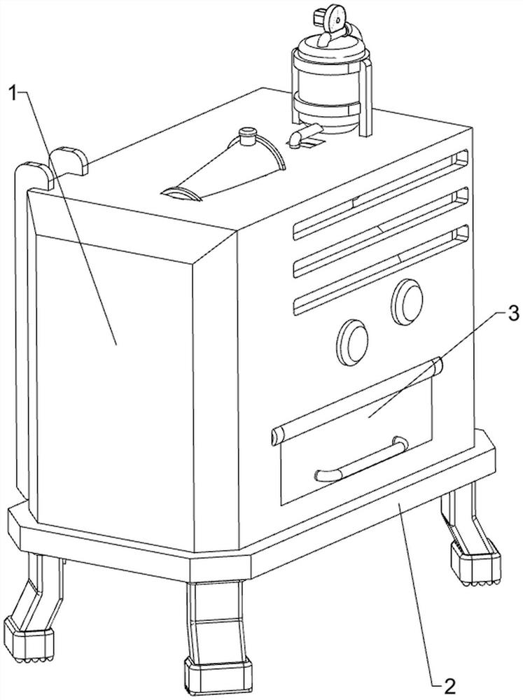
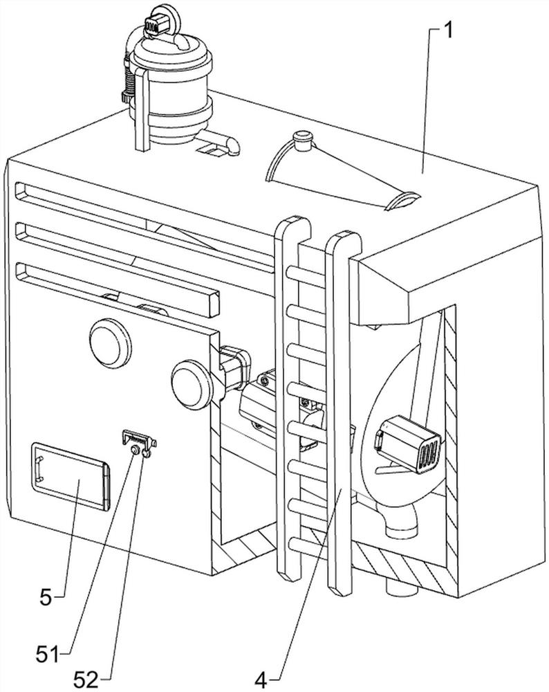
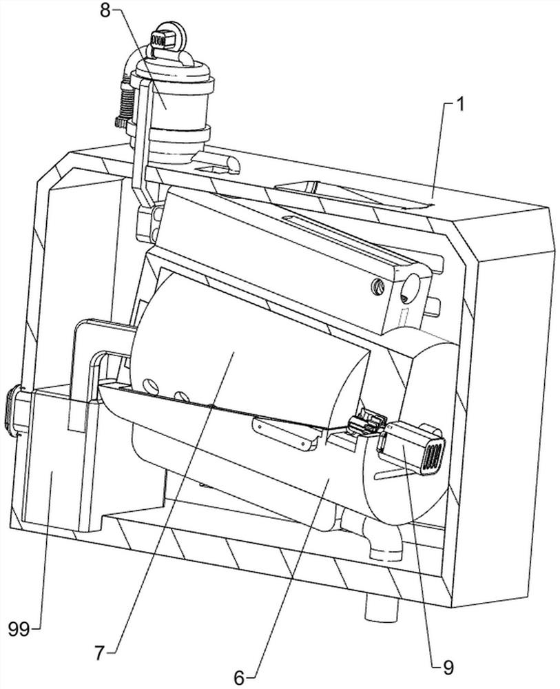
[0041] A kind of industrial wastewater ammonia nitrogen treatment device for river anti-pollution, such as Figure 1-Figure 6 As shown, it includes an airtight bottom box 1, a supporting bottom plate 2, an opening and closing baffle 3, a stressed escalator 4, a start button 51, a stop button 52, an installation bottom cylinder 6, a filter liner 7, a liquid inlet mechanism 8 and a scraper Mechanism 9, the bottom of the airtight bottom box 1 is connected with a support base plate 2 by welding, the lower side of the front part of the airtight bottom box 1 is hingedly provided with an opening and closing baffle 3, and the left side of the outer rear side of the airtight bottom box 1 is connected by welding. The stressed escalator 4, the stressed escalator 4 can be realized to be convenient for people to operate, and the lower right part of the outer rear side of the airtight bottom box 1 is fixedly connected with a start button 51 and a stop button 52, and the stop button 52 is pos...
Embodiment 2
[0046] On the basis of Example 1, such as Figure 7-Figure 9 As shown, a liquid blocking mechanism 10 is also included, and the liquid blocking mechanism 10 includes a second installation box 101, an electric push rod 102, a short limit rod 103, a positioning column 104, a second driven gear 105, and a liquid blocking cylinder 106 , the roller limit plate 107, the force stand 108, the first telescopic sleeve 109, the first return spring 1010, the first photoelectric sensor 1011 and the second photoelectric sensor 1012, and the left side of the bottom cylinder 6 is installed by means of bolts A second installation box 101 is connected, and an electric push rod 102 is connected to the second installation box 101 by means of bolts. Two positioning columns 104 are fixedly connected to the left side of the rear part of the installation bottom cylinder 6, and the two positioning columns 104 slide between them. The short limit rod 103 is fixedly connected with the telescopic rod of t...
Embodiment 3
[0051] On the basis of embodiment 1 and embodiment 2, such as Figure 12-Figure 16 As shown, it also includes a uniform spreading mechanism 12, and the uniform spreading mechanism 12 includes a second transmission assembly 121, a positioning screw 122, a limit roller 123, an engaging groove block 124, a connecting short block 125, a hook spring 126, a spreading Material square tube 127, ejector rod 128, limit guide post 129 and limit spring 1210, the front side rotation type of bottom cylinder 6 top is provided with positioning screw 122, and the right part of positioning screw 122 is connected with the right side of reversing horizontal shaft 114. The second transmission assembly 121 is connected between the parts, the second transmission assembly 121 is composed of two pulleys and a belt, one pulley is installed on the right part of the positioning screw 122, and the other pulley is installed on the right part of the reversing horizontal shaft 114, and the belt winds Between...
PUM
 Abstract
Description
Claims
Application Information
 - R&D
- Intellectual Property
- Life Sciences
- Materials
- Tech Scout
- Unparalleled Data Quality
- Higher Quality Content
- 60% Fewer Hallucinations
Browse by: Latest US Patents, China's latest patents, Technical Efficacy Thesaurus, Application Domain, Technology Topic, Popular Technical Reports.
© 2025 PatSnap. All rights reserved.Legal|Privacy policy|Modern Slavery Act Transparency Statement|Sitemap|About US| Contact US: help@patsnap.com


