Expandable relative positioning device and method based on UWB and camera

A relative positioning and camera technology, applied in measuring devices, instruments, surveying and navigation, etc., can solve the problems of high cost, useless computing power consumption, large time delay, and not suitable for mobile robot applications, so as to improve robustness, Great economic value, the effect of reliable relative bearing measurement

Pending Publication Date: 2022-03-04
浙江大学湖州研究院
View PDF0 Cites 0 Cited by
  • Summary
  • Abstract
  • Description
  • Claims
  • Application Information

AI Technical Summary

Problems solved by technology

The SLAM method requires high computing resources and is expensive, and the solution based on infrastructure such as multiple base stations requires additional equipment deployment work, which is not suitable for the application of mobile robots
When used for relative pose estimation, the above two methods calculate the relative position by obtaining the global coordinates, resulting in useless computing power consumption and large time delay, and the system cannot be expanded
[0007] UWB single-point ranging can obtain centimeter-level accuracy, but relative orientation information cannot be easily obtained
The new technology of Bluetooth 5.1 can obtain the angle of arrival of the signal, but the accuracy is limited and a special antenna is required
Laser ranging can obtain high-precision distance measurement, but requires a highly directional beam, which is not suitable for applications on mobile robots

Method used


Image

  • Expandable relative positioning device and method based on UWB and camera
  • Expandable relative positioning device and method based on UWB and camera
  • Expandable relative positioning device and method based on UWB and camera

Examples


Embodiment 1

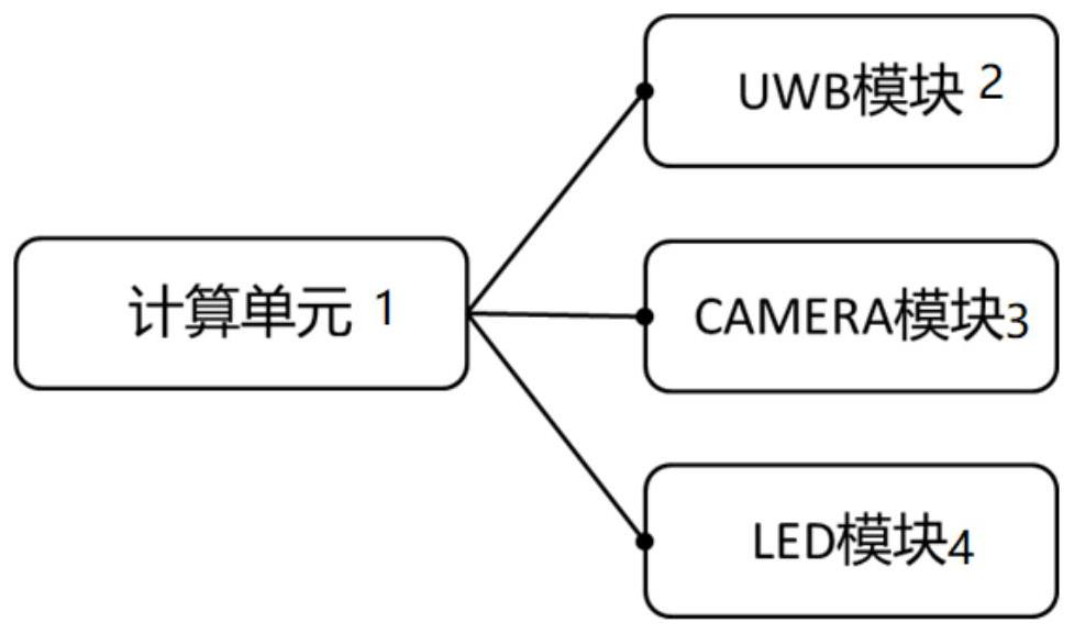
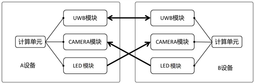
[0037] Such as image 3 As shown, there are two devices, A device 5 and B device 6 . Each device includes a body on which the above-mentioned UWB module 2, CAMERA module 3, light emitting module 4 and computing unit 1 are installed. The UWB module 2 is a UWB antenna protruding from the upper side of the body, the CAMERA module 3 is a camera installed on one side of the body, and the light emitting module 4 is an LED module installed within the FOV range of the CAMERA module 3 .

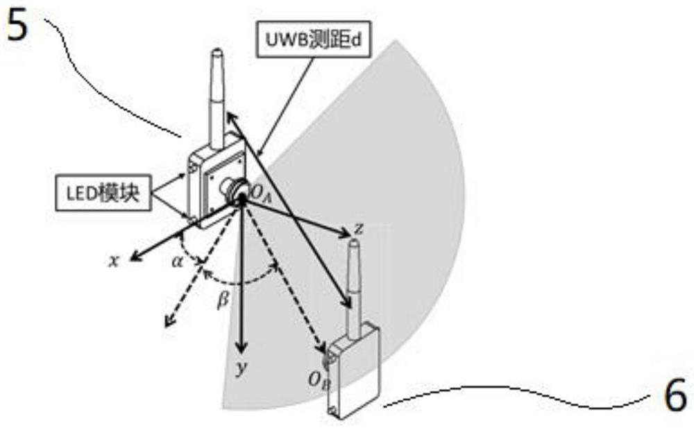
[0038] Next, the orientation of the B device 6 in the A coordinate system will be analyzed by taking the A device 5 as an object. The UWB ranging modules of the A device 5 and the B device 6 can measure the distance d from O_A to O_B. The camera plane of A device 5 is as follows Figure 4 As shown, the B device 6 is within the viewing angle of A, and the coordinates on the camera plane of A are (u, v). Through the pixel coordinates (u, v) and the camera model, it can be obtained that the B device 6...

Embodiment 2

[0040] Such as Figure 5 As shown, the CAMERA module 3 can realize a 360° spherical field of view by configuring two cameras with FOV (field of view) greater than or equal to 180° on the front and rear sides of the main body respectively, and realize the positioning of omnidirectional neighbor modules (such as Figure 6 shown).

Embodiment 3

[0042] Such as Figure 7 As shown, by adopting a UWB module with a built-in on-board antenna, a compact relative positioning device can be realized while reducing the cost.


PUM


Abstract

The invention discloses an expandable relative positioning device based on UWB and a camera, the device comprises a UWB module, a CAMERA module, a light emitting module and a calculation unit which are installed on a body, and the UWB module is used for measuring absolute distance measurement information between the UWB module and the UWB module of at least another adjacent device; the CAMERA module is used for measuring absolute angle measurement information of the at least another device; and the calculation unit collects absolute distance measurement information obtained by the UWB module and absolute angle measurement information obtained by the CAMERA module in real time, and is configured to obtain distance and azimuth information of the at least another adjacent device according to the absolute distance measurement information and the absolute distance measurement information. The invention also discloses a method for carrying out relative positioning by using the equipment.

Description

technical field [0001] The invention relates to a device for relative positioning, more specifically, an expandable device for relative positioning based on UWB and a camera, and a method for relative positioning of the device. Background technique [0002] Relative positioning is very important in multi-robot systems and multi-agent systems. For example, multiple unmanned vehicles perceive the position of adjacent unmanned vehicles in their own coordinate system. It can also be used for multiple robots, handheld devices, and drones. , VR / AR equipment and other systems. Obtaining relative position information is very helpful for navigation, obstacle avoidance, and planning, such as autonomous following, cluster cooperation, and virtual reality. [0003] The current schemes for obtaining relative orientation can be divided into two types, from global to relative methods and direct relative observation methods. The global-to-local method requires that the relevant equipment ...

Claims


Application Information

Patent Timeline
IPC IPC(8): G01C21/00
CPCG01C21/005
Inventor 曹燕军高飞宣驰策
Owner 浙江大学湖州研究院
Why Eureka
Try Eureka