Multi-station numerical control lathe

A CNC lathe and multi-station technology, applied in the field of CNC lathes, can solve problems such as scratches on the surface of parts, affect production, and decline in quality, and achieve the effects of increasing the working radius, improving processing efficiency, and saving time and cost

Pending Publication Date: 2022-03-08
田玉
View PDF0 Cites 2 Cited by
  • Summary
  • Abstract
  • Description
  • Claims
  • Application Information

AI Technical Summary

Problems solved by technology

[0003] Existing CNC lathes mostly use single-station processing. The processing of a single part needs to occupy the entire lathe station, and a new round of part processing can only be performed after completing all processes; and during the processing of parts, although the workpiece will be washed , but it is mainly used for cooling purposes, the flushing force is insufficient, and metal debris may adhere to the surface of the processed parts, which may cause scratches on the surface of the parts during the blanking or accumulation process, resulting in a decline in quality and affecting production; at the same time , ring-shaped metal parts often need to process the outer edge of the workpiece, and the existing CNC machine tools mostly use the external clamping method, which affects the processing of ring-shaped metal parts

Method used


Image

  • Multi-station numerical control lathe
  • Multi-station numerical control lathe
  • Multi-station numerical control lathe

Examples


Embodiment Construction

[0028] In order to make the technical means, creative features, goals and effects achieved by the present invention easy to understand, the present invention will be further described below in conjunction with specific embodiments.

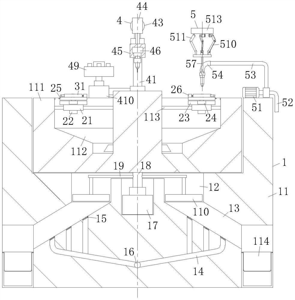
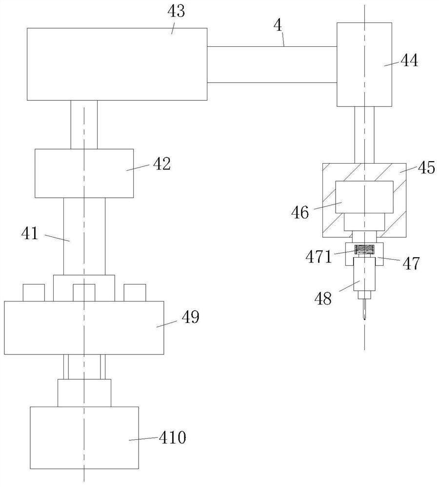
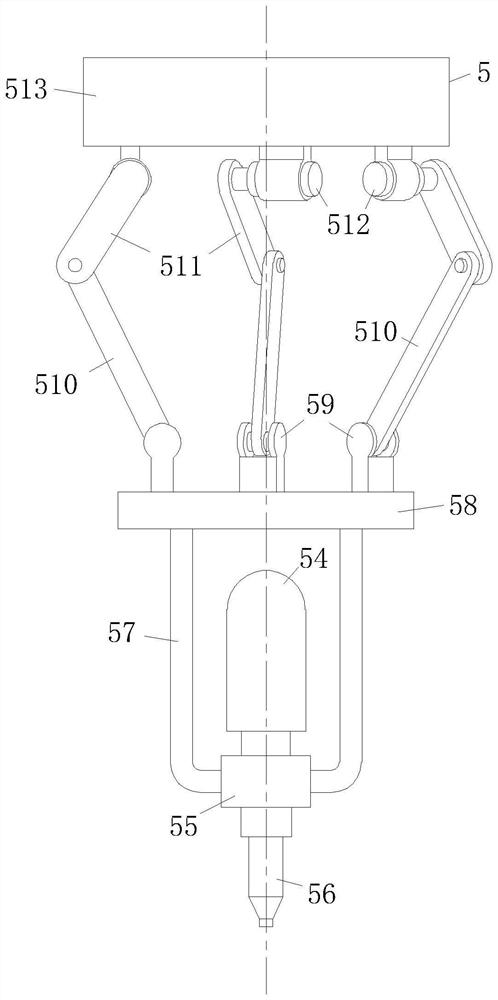
[0029] Such as Figure 1-Figure 8 As shown, a multi-station numerical control lathe according to the present invention includes a diversion mechanism 1, a charging mechanism 2, a limit mechanism 3, a cutting mechanism 4, and a flushing mechanism 5, and the charging mechanism 2 is installed on the diversion mechanism 1 In the four directions, the limit mechanism 3 is movably installed on the top of the charging mechanism 2, the cutting mechanism 4 is installed on one side of the charging mechanism 2, the cutting mechanism 4 is installed on the guide mechanism 1, and the flushing mechanism 5 is installed on the guide mechanism. On the flow mechanism 1, the flushing mechanism 5 is installed on one side of a charging mechanism 2 adjacent to the cutting ...


PUM


Abstract

The invention relates to the field of numerical control lathes, in particular to a multi-station numerical control lathe which comprises a flow guide mechanism, a charging mechanism, a limiting mechanism, a cutting mechanism and a flushing mechanism. The sliding block sleeves the sliding guide rod to form four stations, one station is used for lathe machining, one station is used for flushing, one station is used for discharging, one station is used for feeding, and the four stations are synchronously carried out to form streamline work, so that the time cost is saved, and the machining efficiency is improved; through the cooperation effect of a groove rod and a sliding bolt, the movement trend of a push rod and the movement trend of a limiting sliding bolt are consistent, and therefore the state of a material carrying plate is controlled, the position of a first chuck is controlled, and discharging and feeding are facilitated; the fixed disc needs to be fixedly installed, a second connecting rod is driven to rotate through a sixth motor, then a movable disc is driven to change different directions and angles through a first connecting rod, and therefore the high-pressure punch is driven to wash workpieces from different angles, sufficient cleaning is guaranteed, and the surfaces of the workpieces are prevented from being scratched by metal scraps.

Description

technical field [0001] The invention relates to the field of numerically controlled lathes, in particular to a multi-station numerically controlled lathe. Background technique [0002] CNC lathe is one of the most widely used CNC machine tools at present. It is mainly used for cutting the inner and outer cylindrical surfaces and conical threads of shaft parts or disc parts, and can perform grooving, drilling, reaming, reaming and boring. The CNC machine tool automatically processes the processed parts according to the programmed processing program. [0003] Existing CNC lathes mostly use single-station processing. The processing of a single part needs to occupy the entire lathe station, and a new round of part processing can only be performed after completing all processes; and during the processing of parts, although the workpiece will be washed , but it is mainly used for cooling purposes, the flushing force is insufficient, and metal debris may adhere to the surface of ...

Claims


Application Information

Patent Timeline
Patent Type & Authority Applications(China)
IPC IPC(8): B23B3/00B23B25/00B23Q3/06B23Q7/00B23Q11/00B23Q15/24B08B3/02
CPCB23B3/00B23B25/00B23Q3/06B23Q11/0042B23Q7/00B23Q15/24B08B3/02
Inventor 田玉刘自强
Owner 田玉
Why Eureka
Try Eureka