New energy battery mounting structure

An installation structure, new energy technology, applied in the direction of structural parts, secondary batteries, battery cover/end cover, etc., can solve the problems of reducing the use effect of the installation structure, trouble, affecting the stability of the battery, etc., to improve the cooling effect, improve the Safety and the effect of improving earthquake resistance

Pending Publication Date: 2022-03-08
王新明
View PDF0 Cites 0 Cited by
  • Summary
  • Abstract
  • Description
  • Claims
  • Application Information

AI Technical Summary

Problems solved by technology

[0003] When the current new energy vehicle is driving on a bumpy road, the vibration will be transmitted to the battery part of the new energy vehicle, which will have a continuous impact on the battery structure. Over time, it will affect the stability of the battery in the new energy vehicle and cannot be effectively used. Reduce the impact of vibration on the battery; and the current new energy battery installation structure in the process of battery work, the multiple sets of battery panels inside the battery will gradually generate a lot of heat, the traditional cooling method is difficult for each set of battery panels in the battery. It has a better cooling effect, thereby reducing the use effect of the entire installation structure; at the same time, the current battery installation structure often arranges multiple sets of battery panels side by side and then fixes them with bolts. It is very troublesome to untie the fixing components in the entire battery installation structure, and it is impossible to quickly disassemble and replace the designated damaged battery board

Method used


Image

  • New energy battery mounting structure
  • New energy battery mounting structure
  • New energy battery mounting structure

Examples


Embodiment 1

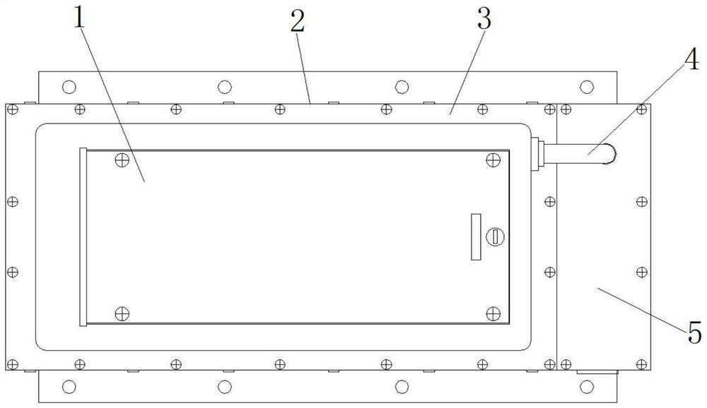
[0038] Example 1, such as Figure 1-7 As shown, when the new energy vehicle encounters a bumpy road during driving, the vibration is gradually transmitted to the battery installation structure, and the buffer spring 606 cooperates with the movable rod 604 to buffer the longitudinal stress on the battery board inside the card holder 601. The fixed spring 602 inside the installation hole 608 cooperates with the movable plate 603 to buffer the lateral stress on the battery board of the card seat 601. Through the two buffer structures, the shock resistance of the new energy battery installation structure can be greatly improved. When it is necessary to replace the damaged battery board inside the designated card holder 601, first open the installation cover 3, and then push the corresponding damaged battery board to the end of the card holder 601 close to the movable plate 603, so that the fixed spring 602 is shortened by force. At this time, the operator can directly take out the...

Embodiment 2

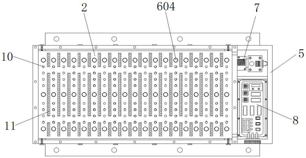
[0039] Example 2, such as Figure 1-7 As shown, when the battery board in the battery installation structure generates a large amount of heat due to work, the air pump 7 is first controlled by the external control panel to blow air into the interior of the installation compartment 17, and then cooperates with the energized semiconductor cooling chip 16 to blow the air into the installation compartment 17. The cold air inside 17 is blown into the inside of the jet chamber 15, and then the cold air is blown into between the multiple groups of battery panels inside the main body compartment 2 through the air outlet 11, and the multiple groups of battery panels are simultaneously cooled by wind, and the bottom of the battery panels generates The heat is transferred to the heat-conducting rod 10 through the heat-conducting plate 9, and the cold air will cool down the surface of the heat-conducting rod 10 in the process of passing through the interior of the air jet chamber 15, and t...


PUM


Abstract

The invention discloses a new energy battery mounting structure which comprises a main body bin, an air injection bin is mounted at the bottom of the main body bin, a side bin is mounted on one side of the main body bin, a mounting bin is mounted at the bottom of the side bin, and a semiconductor chilling plate is mounted at the inner bottom of the mounting bin. A containing assembly is arranged in the main body bin and the air injection bin jointly, and a mounting cover is mounted at the top of the main body bin. Through cooperative use of the air suction bin, the main body bin, the side bin, the air suction pump, the air injection bin, the semiconductor chilling plate and the mounting bin, air is blown into the mounting bin through the air suction pump, and then the electrified semiconductor chilling plate is matched, so that cold air can be blown into the air injection bin; and then the cold air is blown into the plurality of groups of battery panels in the main body bin through the air outlet holes, and the plurality of groups of battery panels are simultaneously subjected to air blowing cooling, so that the cooling effect of the new energy battery mounting structure on the battery panels is further improved, and the new energy battery is always in a better temperature environment.

Description

technical field [0001] The invention relates to the technical field of new energy vehicles, in particular to a new energy battery installation structure. Background technique [0002] New energy vehicles are becoming more and more popular in daily life, especially electric vehicles are powered by vehicle-mounted power supplies, and use motors to drive wheels, which are energy-saving and environmentally friendly. Electric vehicles need to be equipped with new energy batteries, and new energy batteries are large in size. Energy batteries are usually flat and installed on the bottom of the vehicle body through a fixed structure. In order to reduce the waiting time for vehicle charging, charging stations currently provide battery replacement services. Car owners can replace the exhausted battery with the saturated battery. [0003] When the current new energy vehicle is driving on a bumpy road, the vibration will be transmitted to the battery part of the new energy vehicle, whic...

Claims


Application Information

Patent Timeline
Patent Type & Authority Applications(China)
IPC IPC(8): H01M50/242H01M50/244H01M50/249H01M50/271H01M10/613H01M10/625H01M10/6556H01M10/6563H01M10/6572
CPCH01M50/242H01M50/244H01M50/249H01M50/271H01M10/613H01M10/625H01M10/6556H01M10/6563H01M10/6572Y02E60/10
Inventor 王新明
Owner 王新明
Why Eureka
Try Eureka