
Pulse-width modulation (PWM) control circuit based on multiphase direct current (DC)-DC

A step-down converter and control circuit technology, applied in the direction of control/regulation system, output power conversion device, instrument, etc., can solve the problems of increasing mismatch, increasing chip cost, increasing current and phase error between power stages, etc. Achieve the effect of eliminating slope compensation and reducing current mismatch

Pending Publication Date: 2022-03-08
江阴市新际科技有限公司
View PDF3 Cites 0 Cited by
  • Summary
  • Abstract
  • Description
  • Claims
  • Application Information

AI Technical Summary

Problems solved by technology

These integration circuits and detection circuits increase chip cost, increase circuit complexity and increase the risk of mismatch
In order to reduce the problem of uneven current and phase between multiple power stages, the mismatch introduced by the newly added circuit increases the error of current and phase between power stages

Method used


Image

  • Pulse-width modulation (PWM) control circuit based on multiphase direct current (DC)-DC
  • Pulse-width modulation (PWM) control circuit based on multiphase direct current (DC)-DC
  • Pulse-width modulation (PWM) control circuit based on multiphase direct current (DC)-DC

Examples


Embodiment Construction

[0057] In order to enable those skilled in the art to better understand the technical solutions in the present invention, the technical solutions in the embodiments of the present invention will be clearly and completely described below in conjunction with the drawings in the embodiments of the present invention. Obviously, the described The embodiments are only some of the embodiments of the present invention, not all of them. Based on the embodiments of the present invention, all other embodiments obtained by persons of ordinary skill in the art without making creative efforts shall fall within the protection scope of the present invention.

[0058] ginseng Figure 5 As shown, the present invention discloses a PWM control circuit based on a multiphase DC-DC step-down converter, including:

[0059] A multi-phase DC-DC step-down converter comprising n power stages connected in parallel between the input voltage VIN and the output voltage VOUT, each power stage being a single-...


PUM


Abstract

The invention discloses a PWM (Pulse Width Modulation) control circuit based on a multiphase DC-DC (Direct Current-Direct Current) buck converter. The PWM control circuit comprises the multiphase DC-DC buck converter, a clock, a phase distributor, a fixed turn-off time generator and a peak current mode PWM controller. According to the invention, an existing peak current detector and an error amplifier are used for current distribution, and an integral circuit and a detection circuit do not need to be added; the phase distributor can achieve average phase distribution; the fixed turn-off time generator can eliminate slope compensation in peak current mode PWM control and reduce current mismatch caused by slope compensation.

Description

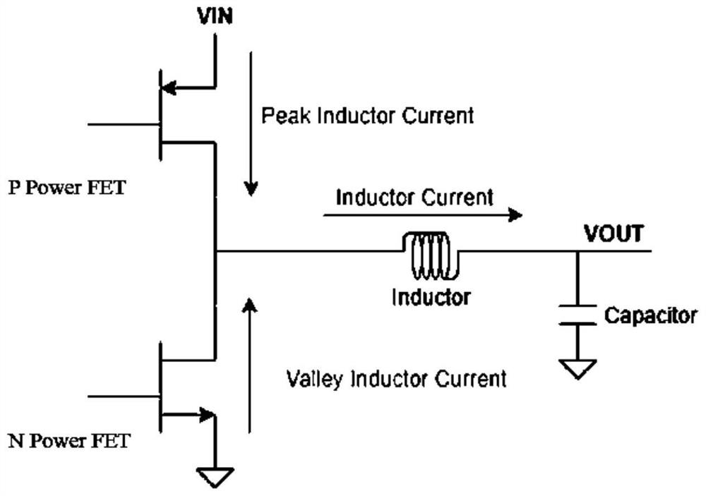
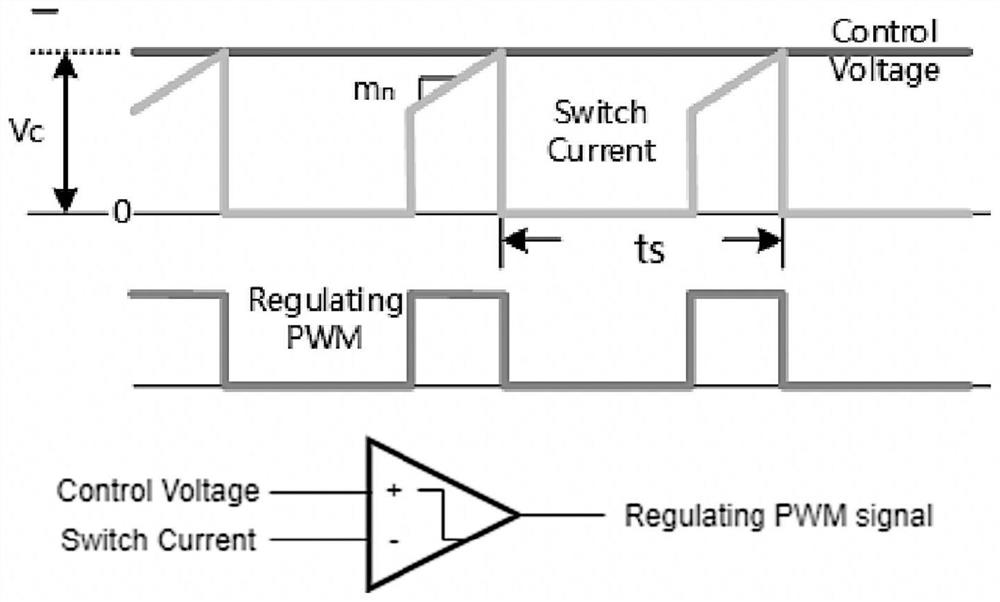
technical field [0001] The invention belongs to the technical field of power management chips, and in particular relates to a PWM control circuit based on a multiphase DC-DC step-down converter. Background technique [0002] A DC-DC step-down converter is a conversion circuit that converts a higher input voltage into a lower output voltage, see figure 1 As shown, it includes two power tubes (P Power FET and N Power FET), a low pass filter (Low Pass Filter) formed by an inductor (Inductor) and a capacitor (Capacitor). One of the power tubes is the main power tube, and the conduction time of the main power tube is the pulse width of the switching square wave. [0003] The DC-DC step-down converter can be controlled by peak current mode PWM control (Peak Current Mode PWM Control), PFM (Pulse-Frequency-Modulation) pulse frequency modulation, fixed off-time mode PFM control (Constant-Off-Time Mode PFM Control ) and other methods to control. combine figure 2 As shown, the pea...

Claims


Application Information

Patent Timeline
IPC IPC(8): H02M3/156H02M1/32
CPCH02M3/156H02M1/32
Inventor 严之嶽尹虎君
Owner 江阴市新际科技有限公司
Learn More