Check patentability & draft patents in minutes with Patsnap Eureka AI!

Wide-dynamic range low-mismatch charge pump circuit applied to phase-locked loop

A wide dynamic range, charge pump technology, applied in the direction of automatic power control, electrical components, etc., can solve problems such as increasing circuit power consumption, area and stability, increasing the difficulty of charge pump circuit design, and increasing circuit complexity, etc. Achieve low power consumption, reduce current mismatch, and ease of integration

Pending Publication Date: 2018-10-26
GUILIN UNIV OF ELECTRONIC TECH
View PDF0 Cites 0 Cited by
  • Summary
  • Abstract
  • Description
  • Claims
  • Application Information

AI Technical Summary

Problems solved by technology

[0004] In order to achieve a higher matching accuracy of charging current and discharging current, the traditional charge pump circuit usually uses an operational amplifier circuit to clamp the voltage of the current mirror and the output terminal, which not only increases the complexity of the circuit, but also increases the overall power consumption of the circuit. , area and stability issues
In order to meet the wide output frequency range of the phase-locked loop, it is usually realized by improving the tuning sensitivity of the voltage-controlled oscillator and widening the voltage dynamic range of the charge pump circuit, but increasing the tuning sensitivity of the voltage-controlled oscillator will introduce a large Noise, in order to ensure the noise characteristics of the phase-locked loop, the dynamic range of the charge pump tuning voltage can be improved, which requires the operational amplifier to achieve rail-to-rail input and output characteristics, further increasing the design difficulty of the charge pump circuit

Method used


Image

  • Wide-dynamic range low-mismatch charge pump circuit applied to phase-locked loop
  • Wide-dynamic range low-mismatch charge pump circuit applied to phase-locked loop
  • Wide-dynamic range low-mismatch charge pump circuit applied to phase-locked loop

Examples


Embodiment Construction

[0022] In order to make the object, technical solution and advantages of the present invention clearer, the present invention will be further described in detail below in combination with specific examples and with reference to the accompanying drawings.

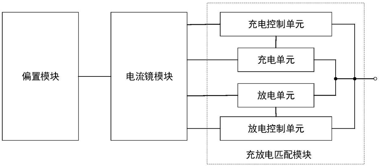
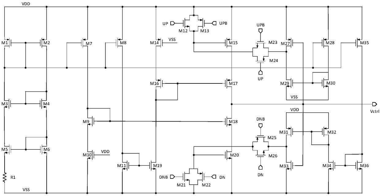
[0023] A wide dynamic range low mismatch charge pump circuit for phase-locked loop applications, such as figure 1 and 2 As shown, it consists of a bias module, a current mirror module and a charge-discharge matching module.

[0024] The bias module is used to generate a bias current to bias the current mirror module and the charge-discharge matching module. The bias module consists of MOS transistors M1, M2, M3, M4, M5, M6 and resistor R1. The MOS tube M1 and the MOS tube M2 are PMOS tubes; the MOS tube M3 , the MOS tube M4 , the MOS tube M5 and the MOS tube M6 are NMOS tubes. The sources of the PMOS transistors M1 and M2 are both connected to the power supply VDD. The gate of the PMOS transistor M1 is connected to the g...


PUM


Abstract

The invention discloses a wide-dynamic range low-mismatch charge pump circuit applied to a phase-locked loop. The wide-dynamic range low-mismatch charge pump circuit comprises a bias module, a currentmirror module and a charging and discharging matching module; the bias module is used for generating a constant current and outputting the constant current to the current mirror module; the current mirror module is used for supplying a bias voltage to a charging control unit, a charging unit, a discharging unit and a discharging control unit in the charging and discharging matching module; the charging control unit and the discharging control unit are used for detecting the output voltage of a charge pump and adjusting the charging current and the discharging current to enable the charging current and the discharging current to be matched; and the charging unit and the discharging unit are used for outputting loads to the charge pump for charging or discharging. According to the charge pump circuit, the output voltage is fed back to the charging control unit and the discharging control unit, so that the charging current and the discharging current of the charge pump are matched in a wide output voltage range; and the charge pump circuit does not need an additional operation amplifier circuit and is simple in structure, good in stability, low in power consumption, easy to integrateand suitable for a high-performance phase-locked loop circuit.

Description

technical field [0001] The invention relates to the technical field of integrated circuits, in particular to a wide dynamic range and low mismatch charge pump circuit applied to a phase-locked loop. Background technique [0002] Phase-locked loops (Phase-locked loops, PLL) is a frequency and phase synchronization technology realized by the principle of feedback control, and its function is to synchronize the clock output by the circuit with its external reference clock. When the frequency or phase of the reference clock changes, the phase-locked loop will detect this change and adjust the output frequency through its internal feedback system until the two are re-synchronized. This synchronization is also called "phase-locked". PLLs are used in many fields, such as wireless communication, digital TV, broadcasting, etc. Specific applications include but are not limited to: wireless communication system transceiver module (Transceiver), data and clock recovery circuit (Clock a...

Claims


Application Information

Patent Timeline
IPC IPC(8): H03L7/18
CPCH03L7/18
Inventor 段吉海张久民徐卫林韦保林
Owner GUILIN UNIV OF ELECTRONIC TECH
Features
  • R&D
  • Intellectual Property
  • Life Sciences
  • Materials
  • Tech Scout
  • Unparalleled Data Quality
  • Higher Quality Content
  • 60% Fewer Hallucinations
Learn More