Wire cord fabric detection and calibration device and detection and calibration method

A technology for detecting and calibrating devices and steel cords, applied in the direction of material magnetic variables, etc., can solve the problems of different initial excitation magnetic field signals of array magnetic field units, the original output of magneto-sensitive elements deviates from the initial installed value, and the output of array magneto-sensitive elements is not the same. , to achieve a wide range of applications, increase the distance, and meet the effect of calibration

Pending Publication Date: 2022-03-11
WEIHAI HUALING OPTO ELECTRONICS CO LTD
View PDF9 Cites 2 Cited by
  • Summary
  • Abstract
  • Description
  • Claims
  • Application Information

AI Technical Summary

Problems solved by technology

[0005] (1) The discreteness between the magnetic sensitive elements of the array causes the initial state of each magnetic sensitive element to be different, and the initial excitation magnetic field signals of the magnetic field units of the array are different, resulting in different magnetic fields applied to each magnetic sensitive element when no steel cord passes through, Ultimately, the original output of each array magnetic sensor is different, which brings difficulties to subsequent image defect detection;
[0006] (2) When the steel cord is continuously conveyed on the detection device, due to environmental changes and continuous impact on the magnetic sensor and the magnetic field unit after the steel cord is magnetized, the initial excitation magnetic field changes, making the original output of the magnetic sensor deviate from the initial installed value , and cause the background magnetic image to be uneven, which greatly interferes with the judgment of the subsequent image defect detection unit, and the detection device installed on the production line is always affected by the steel cord, which is difficult to pass through the influence of the steel cord on the initial excitation magnetic field. Eliminate the method of calibrating the detection device at a fixed position;
[0007] (3) Especially when the format detected by the detection device is very long and the production line does not have a large horizontal horizontal space, how to conveniently and accurately calibrate the detection device has not proposed a feasible method at present

Method used


Image

  • Wire cord fabric detection and calibration device and detection and calibration method
  • Wire cord fabric detection and calibration device and detection and calibration method
  • Wire cord fabric detection and calibration device and detection and calibration method

Examples


Embodiment 1

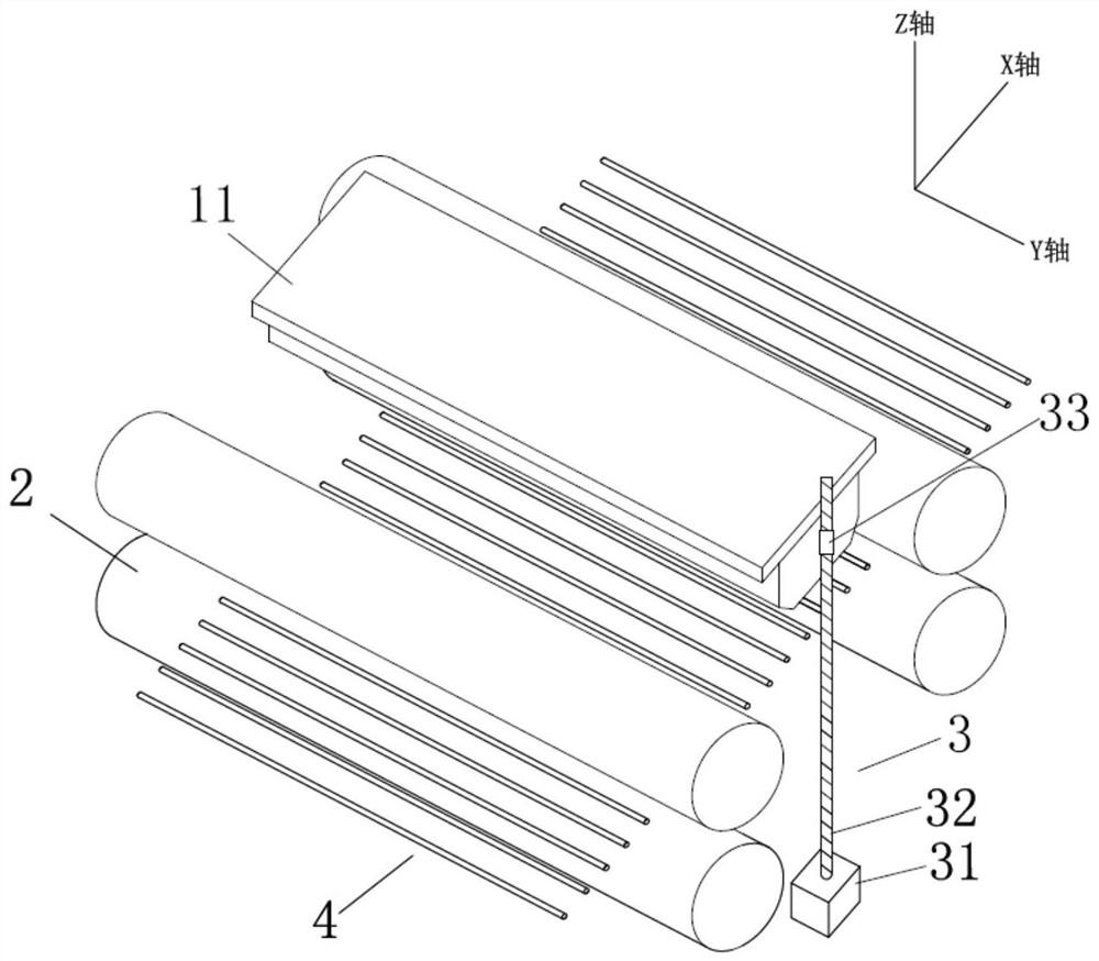
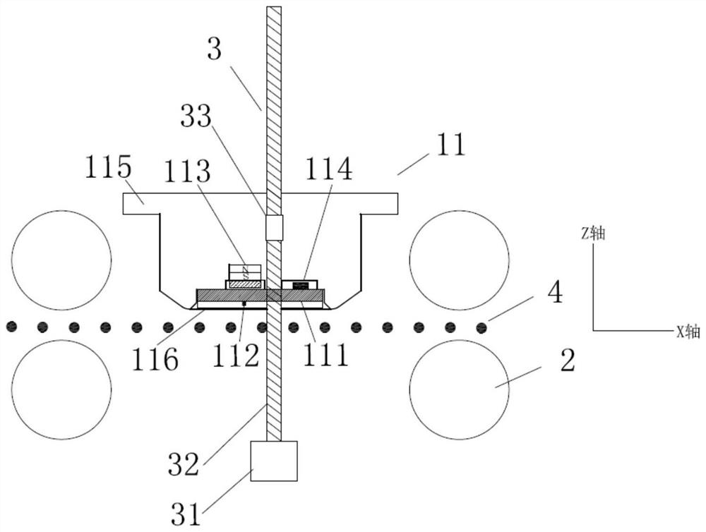
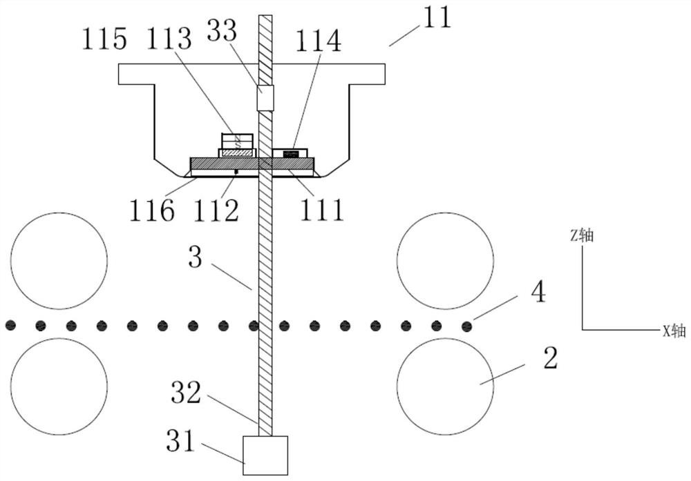
[0084] Such as Figure 1 to Figure 3 As shown, this embodiment provides a steel cord detection and calibration device, including a magnetic sensor module 11, four rollers 2 and a lifting mechanism.

[0085] The magnetic sensor module 11 is arranged directly below the web of the steel cord 4, and includes a substrate 111 made of PCB material. 4320 magnetic sensitive elements 112 are arranged at equal intervals of 0.5 mm to form an effective scanning width of 2160 mm and obtain detection signals and calibration signals, both of which are magnetic field signals, specifically, voltage signals reflecting the magnitude of the magnetic field; The surface of the base plate 111 facing away from the steel cord 4 is provided with a magnetic unit 113 and a processing unit 114. The magnetic unit 113 includes a plurality of magnets arranged at equal intervals along the Y-axis direction. The processing unit 114 communicates with the magnetosensitive The element 112 is electrically connected...

Embodiment 2

[0105] Embodiment 2 provides another embodiment of the steel cord detection and calibration device of the present application, Figure 4 is a perspective view of this embodiment, Figure 5 It is a side view of this embodiment in the detection state, Figure 6 It is a side view of this embodiment in a calibration state.

[0106] Such as Figure 4 to Figure 6As shown, the difference between this embodiment and Embodiment 1 is that the two rollers 2 are located under the steel cord 4 for supporting the steel cord 4, and the two ends of the rollers 2 exceed the edge of the steel cord 4, and the four sets of lifting dies Group 3 respectively corresponds to the four ends of the two rollers 2 , and the receiving member 33 of each group is connected to one end.

[0107] When using the steel cord detection and calibration device of this embodiment to detect and calibrate the steel cord 4, the four motors 31 rotate at the same speed and direction of rotation, driving the two rollers ...

Embodiment 3

[0109] Embodiment 3 provides another embodiment of the steel cord detection and calibration device of the present application, Figure 7 is a perspective view of this embodiment, Figure 8 It is a side view of this embodiment in the detection state, Figure 9 It is a side view of this embodiment in a calibration state.

[0110] The difference between this embodiment and Embodiment 2 is that an opposing magnetic module 12 is added, and the opposing magnetic module 12 and the magnetic sensor module 11 are oppositely arranged on both sides of the steel cord 4, and the two keep a fixed distance of 10 cm, and the opposite The magnetic module 12 includes a facing magnetic unit 121 formed by arranging magnets of a plurality of strong magnetic structures along the Y direction. Inserted and fixed; the steel cord 4 is driven up and down between the magnetic sensor module 11 and the opposing magnetic module 12 under the drive of the roller 2. Obviously, in the above-mentioned embodimen...


PUM


Abstract

The invention provides a wirecord fabric detection and calibration device and method, the detection and calibration device comprises a detection mechanism, a bearing mechanism and a lifting mechanism, the detection mechanism comprises a magnetic sensor module, the magnetic sensor module comprises a substrate, a plurality of magnetic sensitive elements, a processing unit and a back magnetic unit, and the magnetic sensor module is used for acquiring a detection signal and a calibration signal; the bearing mechanism comprises a plurality of rollers which are arranged below the wirecord fabric and distributed on the two sides of the detection mechanism and is used for bearing the wirecord fabric, and the lifting mechanism is used for adjusting the distance between the breadth of the wirecord fabric and the magnetic sensor module. The wirecord fabric detection and calibration device provided by the invention can eliminate the influence of wirecord fabric on the calibration process, is particularly suitable for a large-format wirecord fabric production line, is convenient to operate and easy to implement under the conditions that the field space is limited and the detection device cannot slide out of the workbench, can meet the requirements of calibration and scanning precision, and is suitable for large-format wirecord fabric production lines. The application range is wide.

Description

technical field [0001] The present application relates to the field of industrial non-destructive testing, in particular to a detection and calibration device and method capable of detecting defects in steel cords. Background technique [0002] Steel cord is an important part of truck tires. It is composed of an outer rubber layer and steel cords wrapped in the rubber layer at equal intervals. As a belt layer of truck tires, it provides important support for strengthening the structural strength and bearing capacity of truck tires. During the manufacturing process of steel cord, due to the influence of production equipment and process flow, the steel wires in the steel cord may have uneven distribution such as bending, dislocation, disconnection, crossing, etc. If the distribution of steel wires in the steel cord cannot be detected in real time, then It will have an adverse effect on the quality of the steel cord, and directly affect the performance and safety of the truck t...

Claims


Application Information

Patent Timeline
Patent Type & Authority Applications(China)
IPC IPC(8): G01N27/82
CPCG01N27/82
Inventor 戚务昌林永辉王虎岩孙晓锋
Owner WEIHAI HUALING OPTO ELECTRONICS CO LTD
Why Eureka
Try Eureka