Duplex stay wire and coil gripping fastening device for power transmission line
A technology for fastening devices and power transmission lines, which is applied in the directions of electromechanical devices, circuits, transformer/inductor coils/windings/connections, etc. There are no problems such as better position marking, so as to achieve the effect of improving safety and reliability, saving time and effort in installation, and convenient fastening and disassembly
- Summary
- Abstract
- Description
- Claims
- Application Information
AI Technical Summary
Problems solved by technology
Method used
Image
Examples
Embodiment 1
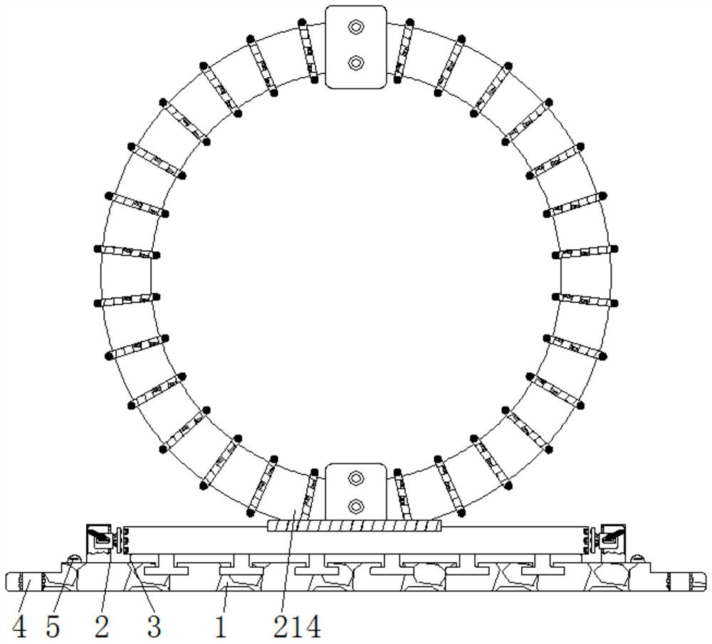
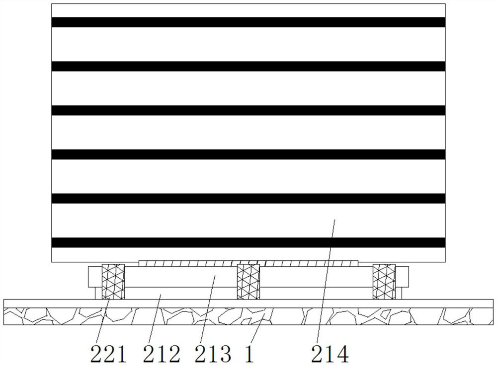
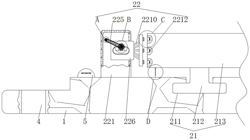
[0025] see figure 1 - Image 6 , a double-guy wire choke fastening device for a power transmission line, comprising a mounting plate 1, a positioning mechanism 2 is movably connected to the outside of the mounting plate 1, and the positioning mechanism 2 includes a clamping assembly 21 for coordinating and positioning the choke coil, and a positioning mechanism for the choke The fixed assembly 22 is fastened in place, the clip assembly 21 is movably connected to the outside of the installation board 1 , and the fixed assembly 22 is movably connected to the outside of the installation board 1 .
[0026] The clamping assembly 21 includes a guide groove 211, a slider 212, a receiving plate 213, and an electric coil 214. The surface of the mounting plate 1 is provided with a guide groove 211, and the inner side of the guide groove 211 is slidably connected with a slider 212, and the outside of the slider 212 is fixed A receiving plate 213 is connected, and an electric coil 214 is...
Embodiment 2
[0030] see figure 1 , Figure 7 , a double-guy wire choke fastening device for a power transmission line, comprising a mounting plate 1, a positioning mechanism 2 is movably connected to the outside of the mounting plate 1, and the positioning mechanism 2 includes a clamping assembly 21 for coordinating and positioning the choke coil, and a positioning mechanism for the choke The fixed assembly 22 is fastened in place, the clip assembly 21 is movably connected to the outside of the installation board 1 , and the fixed assembly 22 is movably connected to the outside of the installation board 1 .
[0031] The outside of the mounting plate 1 is movably connected with an installation guide mechanism 3 for marking. The installation guide mechanism 3 includes a direction groove 301 and an identification bar 302. The surface of the installation plate 1 is provided with a direction groove 301, and the outside of the receiving plate 213 is fixedly connected with an identification bar. ...
Embodiment 3
[0034] see figure 1 - Figure 7, a double-guy wire choke fastening device for a power transmission line, comprising a mounting plate 1, a positioning mechanism 2 is movably connected to the outside of the mounting plate 1, and the positioning mechanism 2 includes a clamping assembly 21 for coordinating and positioning the choke coil, and a positioning mechanism for the choke The fixed assembly 22 is fastened in place, the clip assembly 21 is movably connected to the outside of the installation board 1 , and the fixed assembly 22 is movably connected to the outside of the installation board 1 .
[0035] The clamping assembly 21 includes a guide groove 211, a slider 212, a receiving plate 213, and an electric coil 214. The surface of the mounting plate 1 is provided with a guide groove 211, and the inner side of the guide groove 211 is slidably connected with a slider 212, and the outside of the slider 212 is fixed A receiving plate 213 is connected, and an electric coil 214 is...
PUM
 Abstract
Description
Claims
Application Information
 - R&D
- Intellectual Property
- Life Sciences
- Materials
- Tech Scout
- Unparalleled Data Quality
- Higher Quality Content
- 60% Fewer Hallucinations
Browse by: Latest US Patents, China's latest patents, Technical Efficacy Thesaurus, Application Domain, Technology Topic, Popular Technical Reports.
© 2025 PatSnap. All rights reserved.Legal|Privacy policy|Modern Slavery Act Transparency Statement|Sitemap|About US| Contact US: help@patsnap.com


