Apparatus for exhaust gas retreatment

A technology for equipment and exhaust gas, applied in the field of exhaust gas/exhaust equipment, which can solve the problems of nitrogen oxide removal and exhaust gas reprocessing not being optimally solved.

Pending Publication Date: 2022-03-11
CPT GRP GMBH
View PDF4 Cites 0 Cited by
  • Summary
  • Abstract
  • Description
  • Claims
  • Application Information

AI Technical Summary

Problems solved by technology

[0004] The devices of the prior art have the particular disadvantage that the aftertreatment of the exhaust gases is not optimally addressed, since nitrogen oxides in particular cannot be sufficiently removed from the exhaust gases in the various operating situations of the motor vehicle

Method used


Image

  • Apparatus for exhaust gas retreatment
  • Apparatus for exhaust gas retreatment

Examples


Embodiment Construction

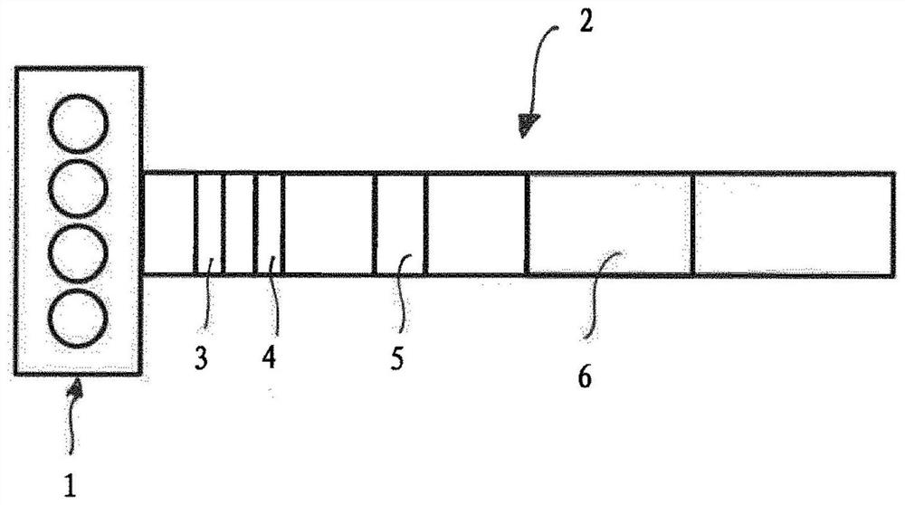
[0024] figure 1 An internal combustion engine 1 is shown. The exhaust gases of the internal combustion engine 1 are conducted into an exhaust duct 2 , which is the flow path for the exhaust gases. A hydrocarbon trap 3 and a nitrogen oxide adsorber 4 are arranged in the flow path 2 . They can also be arranged in reverse order. An electrically heatable heating catalytic converter 5 and then at least one main catalytic converter with reference numeral 6 , which can be, for example, an oxidation catalytic converter or an SCR catalytic converter, are arranged downstream in the direction of flow.

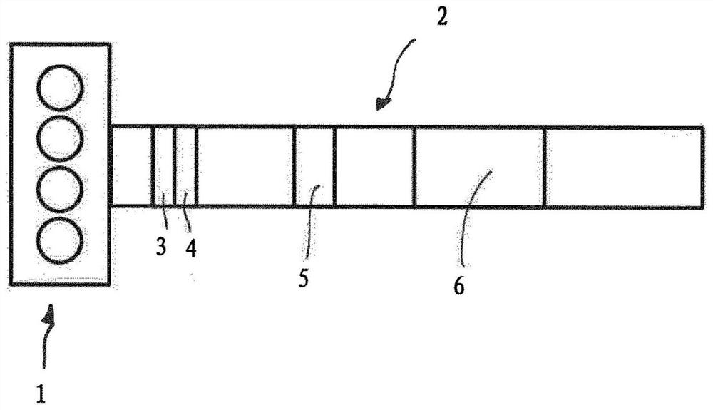
[0025] figure 2 Similar structures are shown, therefore the same reference numerals are used. and figure 1 The difference is that the hydrocarbon trap 3 and the nitrogen oxide adsorber 4 are designed in combination as a common component. Here too, the sequence of the hydrocarbon trap and the nitrogen oxide adsorber can be reversed.

[0026] figure 1 and figure 2 The examples in...


PUM


Abstract

The invention relates to a device for treating exhaust gas of an internal combustion engine (1). The invention relates to a device for the chemical conversion of at least one exhaust gas component, comprising at least one main catalyst (6) for the chemical conversion of at least one exhaust gas component, a hydrocarbon trap (3) for the temporary storage of hydrocarbons, a nitrogen oxide adsorber (4) for the temporary storage of nitrogen oxides, and an electrically heatable heating catalyst (5), the components (3, 4, 5, 6) are arranged in a spatially limited flow path (2) and are sequentially flowed through.

Description

technical field [0001] The invention relates to a device for treating the exhaust gas / exhaust gas of an internal combustion engine, which has at least one main catalyst for the chemical conversion of at least one exhaust gas component, a hydrocarbon trap for the temporary storage of hydrocarbons A collector, a nitrogen oxide adsorber for temporary storage of nitrogen oxides, and an electrically heated heated catalytic converter, wherein the above-mentioned components are arranged in a space-restricted flow path and flow through them sequentially. Background technique [0002] It is known to use so-called HC traps or hydrocarbon traps in the exhaust tract for the purpose of exhaust gas aftertreatment. The purpose of their use is to reduce the hydrocarbons entrained in the exhaust gases, such as especially unburned fuel. Such HC traps are formed, for example, from zeolite-coated monolithic catalyst supports. [0003] DE 691 27 377 T2 discloses the use of HC traps in exhaust ...

Claims


Application Information

Patent Timeline
Patent Type & Authority Applications(China)
IPC IPC(8): F01N3/08F01N3/20
CPCF01N3/0814F01N3/0835F01N3/0842F01N3/2013F01N3/2066F01N2240/16Y02T10/12B01D53/9486B01D2255/91B01D2255/912B01D2255/9155F01N3/28
Inventor R·布鲁克
Owner CPT GRP GMBH
Why Eureka
Try Eureka