
Polarized light endoscope device, camera, and camera optical system

An optical system and polarized light technology, applied in the field of endoscopy, can solve the problems of undetectable targets, blurred targets, reflected light scattering, etc., and achieve the effects of continuous clear surgical field of view, large detection depth, and improved safety

Pending Publication Date: 2022-03-15
CHONGQING XISHAN SCI & TECH
View PDF8 Cites 1 Cited by
  • Summary
  • Abstract
  • Description
  • Claims
  • Application Information

AI Technical Summary

Problems solved by technology

Scattered light will affect the imaging clarity, cause the target to be blurred, and even cause the target to be undetectable
In clinical operations using endoscopic devices (such as orthopedic surgery, urological surgery, gynecological surgery, etc.), under normal saline medium, the operation cavity is filled with normal saline, blood, bone residue, soft tissue residue and stone particles, etc. These substances constitute a non-homogeneous medium, so the reflected light of such medium will cause scattering, which will affect the imaging clarity of the endoscopic device
In this case, the camera optical system used for endoscopic devices in the prior art cannot solve the aforementioned problems, resulting in blurred surgical field of view, affecting the safety and effectiveness of surgery

Method used


Image

  • Polarized light endoscope device, camera, and camera optical system
  • Polarized light endoscope device, camera, and camera optical system
  • Polarized light endoscope device, camera, and camera optical system

Examples


Embodiment Construction

[0024] The present invention will be further described in detail below through specific embodiments in conjunction with the accompanying drawings. Wherein, similar elements in different implementations adopt associated similar element numbers. In the following implementation manners, many details are described for better understanding of the present application. However, those skilled in the art can readily recognize that some of the features can be omitted in different situations, or can be replaced by other elements, materials, and methods. In some cases, some operations related to the application are not shown or described in the description, this is to avoid the core part of the application being overwhelmed by too many descriptions, and for those skilled in the art, it is necessary to describe these operations in detail Relevant operations are not necessary, and they can fully understand the relevant operations according to the description in the specification and genera...


PUM

PropertyMeasurementUnit
Focal lengthaaaaaaaaaa

Abstract

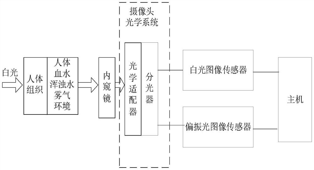
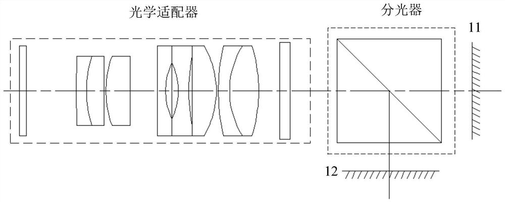
The invention mainly discloses a polarized light endoscope device camera optical system. The polarized light endoscope device camera optical system comprises an optical adapter and an optical splitter which are sequentially arranged from the object side to the image side in the axial direction. The optical splitter has an optical characteristic of selecting the wavelength of the light wave into two wave bands of 380 nm-lambda and lambda-700 nm, and reflects the light wave with the wavelength of 380 nm-lambda and transmits the light wave with the wavelength of lambda-700 nm at the same time, or transmits the light wave with the wavelength of 380 nm-lambda and reflects the light wave with the wavelength of lambda-700 nm at the same time; and lambda is an arbitrary value in the range of 600 nm to 670 nm. After the light waves are split, the light waves with the wavelength of 380 nm to lambda are imaged on the white light image sensor, the light waves with the wavelength of lambda to 700 nm are imaged on the polarized light image sensor, the polarized light endoscope device can simultaneously obtain common white light images and polarized light images in an operation, the polarized light imaging can provide clearer images, the operation field in the operation is kept clear continuously, and the operation efficiency is improved. And the safety and effectiveness of the operation are improved.

Description

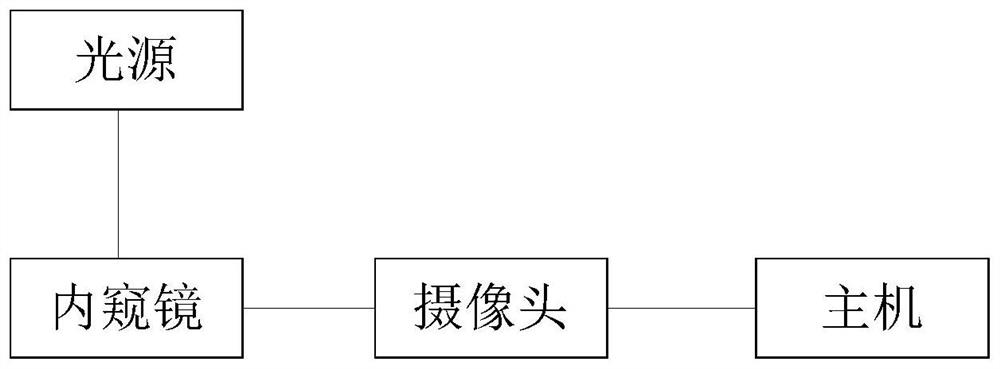
technical field [0001] The invention relates to the technical field of endoscopes, in particular to a polarized light endoscope device. Background technique [0002] Medical endoscope is a medical electronic optical instrument that can be inserted into the cavity of the human body and organs for direct observation, diagnosis and treatment. It uses an extremely small optical lens to image the object in the cavity to be observed through a tiny objective lens The system performs optical imaging, then sends the optical imaging to the image processing host, and finally outputs the image-processed observation image on the display screen for observation and diagnosis by doctors. [0003] Please refer to figure 1 As shown, the current endoscope device as a whole includes a light source, an endoscope, a camera and a host. Among them, the optical system of the camera generally includes an optical adapter lens, which is divided into a fixed focal length adapter (ie: optical fixed foc...

Claims


Application Information

Patent Timeline
IPC IPC(8): A61B1/00A61B1/04G02B23/24
CPCA61B1/00064A61B1/00131A61B1/00163A61B1/04G02B23/243G02B23/2484A61B1/00188
Inventor 郭毅军刘剑
Owner CHONGQING XISHAN SCI & TECH
Learn More