Ash conveying system transformation method

An ash conveying and ash storage technology, applied in conveyors, manufacturing tools, transportation and packaging, etc., can solve the problems of difficulty in guaranteeing the personal safety of maintenance personnel, reducing the fluidization effect of ash unloading, affecting the environmental sanitation of the plant area, etc., to increase the flow rate. effect, avoid squeeze congestion, and facilitate maintenance

Pending Publication Date: 2022-03-15
HUAIBEI MINING IND
View PDF0 Cites 0 Cited by
  • Summary
  • Abstract
  • Description
  • Claims
  • Application Information

AI Technical Summary

Problems solved by technology

[0002] The original ash conveying chute was relatively large (4.5 meters high on the north side and 1.5 meters high on the south side). Due to the relatively small volume of the ash storage, the chute assumed part of the ash storage function in the early stage. After the chute was full of ash, the fluidized cloth at the bottom was affected The waste ash is squeezed and congested, which greatly reduces the fluidization effect during ash unloading, so that part of the desulfurized ash accumulates for a long time. When the chute shell is corroded, aged and cracked, and the waste ash is hardened by moisture after rain, the hardness is relatively high, and the manhole opening of the chute is relatively large. Small, the chute is not equipped with a construction and maintenance platform, and the working height is 15 meters. It is difficult to guarantee the personal safety of the maintenance personnel. After congestion, a large amount of waste ash will be scattered on the ground, seriously affecting the environmental sanitation of the factory area

Method used


Image

  • Ash conveying system transformation method

Examples


Embodiment 1

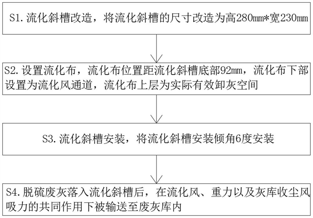
[0045] see figure 1 , the application provides a method for reforming the ash conveying system, comprising the following steps:

[0046] S1. Transformation of the fluidization chute, transforming the size of the fluidization chute to 280mm high*230mm wide;

[0047] S2. Set the fluidization cloth, the position of the fluidization cloth is 92mm away from the bottom of the fluidization chute, the lower part of the fluidization cloth is set as the fluidization air channel, and the upper layer of the fluidization cloth is the actual and effective ash discharge space;

[0048] S3. Install the fluidization chute, install the fluidization chute with an inclination angle of 6 degrees;

[0049] S4. After the desulfurization waste ash falls into the fluidization chute, it is transported to the waste ash storage under the joint action of fluidization wind, gravity and dust collection wind suction of the ash storage.

[0050] In this embodiment, the fluidization chute includes a bottom p...

Embodiment 2

[0071] The difference with Example 1 is:

[0072] The masterbatch includes the following raw materials in parts by weight: 8-32 parts of low-density polyethylene, 36 parts of EVA, 10 parts of lubricant, 12 parts of porous inorganic matter and 3 parts of anti-aging agent; the EVA is selected from ethylene-acetic acid Ethylene copolymer; the porous inorganic substance is selected from diatomaceous earth.

[0073] In the present embodiment, the preparation method of the masterbatch comprises the following steps:

[0074] S301. Add low-density polyethylene, EVA, lubricant, and porous inorganic matter in parts by weight to the high-speed mixer in sequence;

[0075] S302. stirring for 30 minutes;

[0076] S303. Add anti-aging agent, and discharge after stirring for 8 minutes;

[0077] S304. Use a twin-screw extruder or internal mixer to granulate, and then discharge the masterbatch.

[0078] In this embodiment, the stirring speed in S302 is 1000 r / min, and the stirring speed in ...

Embodiment 3

[0080] The difference with embodiment 2 is:

[0081] The masterbatch includes the following raw materials in parts by weight: 20 parts of low-density polyethylene, 20 parts of EVA, 8 parts of lubricant, 8 parts of porous inorganic matter and 2 parts of anti-aging agent; the EVA is selected from the group consisting of ethylene-vinyl acetate copolymer matter; the porous inorganic matter is selected from zeolites.

[0082] In the present embodiment, the preparation method of the masterbatch comprises the following steps:

[0083] S301. Add low-density polyethylene, EVA, lubricant, and porous inorganic matter in parts by weight to the high-speed mixer in sequence;

[0084] S302. stirring for 20 minutes;

[0085] S303. Add anti-aging agent, stir for 6 minutes and discharge;

[0086] S304. Use a twin-screw extruder or internal mixer to granulate, and then discharge the masterbatch.

[0087] In this embodiment, the stirring speed in S302 is 1200r / min, and the stirring speed in S...


PUM


Abstract

The invention provides an ash conveying system transformation method, and belongs to the technical field of desulfurization, denitrification and dust removal. Comprising the following steps: S1, transforming a fluidization chute: transforming the size of the fluidization chute to be 280mm in height and 230mm in width; s2, fluidization cloth is arranged, the distance between the position of the fluidization cloth and the bottom of the fluidization chute is 92 mm, a fluidization air channel is arranged on the lower portion of the fluidization cloth, and the upper layer of the fluidization cloth is an actual effective ash discharging space; s3, a fluidization chute is installed, wherein the fluidization chute is installed at the installation inclination angle of 6 degrees; and S4, after the desulfurized waste ash falls into the fluidization chute, conveying the desulfurized waste ash into a waste ash silo under the combined action of fluidization air, gravity and suction force of dust collection air of the ash silo. After the desulfurization waste ash modified by the device falls into a new fluidization chute, the condition that a large amount of desulfurization waste ash is accumulated before does not exist, and the desulfurization waste ash can be quickly conveyed into the waste ash silo under the combined action of fluidization air, gravity and dust collection air suction of the ash silo, so that extrusion congestion is avoided, the condition that part of desulfurization ash is accumulated for a long time is reduced, the fluidization effect during ash unloading is improved, and the service life of the desulfurization waste ash is prolonged. In addition, staff maintenance is facilitated, and personal safety is improved.

Description

technical field [0001] This application relates to the technical field of desulfurization, denitrification and dust removal, and specifically relates to a method for transforming an ash conveying system. Background technique [0002] The original ash conveying chute was relatively large (4.5 meters high on the north side and 1.5 meters high on the south side). Due to the relatively small volume of the ash storage, the chute assumed part of the ash storage function in the early stage. After the chute was full of ash, the fluidized cloth at the bottom was affected The waste ash is squeezed and congested, which greatly reduces the fluidization effect during ash unloading, so that part of the desulfurized ash accumulates for a long time. When the chute shell is corroded, aged and cracked, and the waste ash is hardened by moisture after rain, the hardness is relatively high, and the manhole opening of the chute is relatively large. Small, the chute is not equipped with a construc...

Claims


Application Information

Patent Timeline
IPC IPC(8): B65G53/16B65G53/38B23P23/04D03D15/292D03D15/50C08L23/08C08L23/06C08K7/26
CPCB65G53/16B65G53/38B23P23/04D03D15/292D03D15/50C08L23/0853C08L23/06C08L2207/066C08K7/26
Inventor 李果
Owner HUAIBEI MINING IND
Why Eureka
Try Eureka