
System for synthesizing methane by co-electrolyzing H2O and CO2 through fuel cell

A technology for synthesizing methane and fuel cells, which can be used in fuel cells, fuel cell additives, and fuel cell heat exchange.

Pending Publication Date: 2022-03-15
北京思伟特新能源科技有限公司
View PDF2 Cites 0 Cited by
  • Summary
  • Abstract
  • Description
  • Claims
  • Application Information

AI Technical Summary

Problems solved by technology

[0003] However, the fuel produced by the existing SOEC system is hydrogen, which is too active and has problems in safety

Method used


Image

  • System for synthesizing methane by co-electrolyzing H2O and CO2 through fuel cell
  • System for synthesizing methane by co-electrolyzing H2O and CO2 through fuel cell

Examples


Embodiment

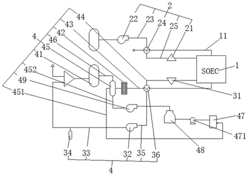
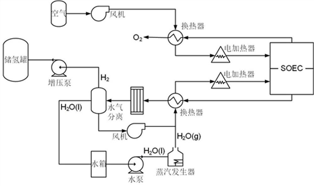
[0021] Examples, please refer to Figure 1-2 , a fuel cell co-electrolysis of H 2 O and CO 2 Synthetic methane system, including SOEC1, air compression heating system 2, circulating hydrocarbon compensation system 3 and methane preparation system 4;

[0022] The air compression heating system 2: After the air is introduced, it is heated by the first electric heater 21 and then introduced into SOEC1 to electrolyze CO and O 2 , in the O 2 discharge;

[0023] The circulating hydrocarbon compensation system 3: the remaining CO and CO in the process of evaporating water and preparing methane 2 After being heated by the second electric heater 31 together with water vapor, it is introduced into SOEC1 for electrolytic hydrogen replenishment;

[0024] The methane preparation system 4: CO, H after electrolysis in SOEC1 2 Separated with water vapor to produce CO through the methanation reactor 41 2 and CH 4 Circulation and discharge are in progress.

[0025] Please refer to fig...


PUM


Abstract

The invention provides a system for synthesizing methane through co-electrolysis of H2O and CO2 by a fuel cell. The system comprises an SOEC, an air compression heating system, a circulating hydrocarbon compensation system and a methane preparation system, the air compression heating system is used for introducing air, heating the air through a first electric heater, introducing SOEC for electrolysis to generate CO and O2, and discharging O2; according to the circulating type hydrocarbon compensation system, water is evaporated, and CO, CO2 and water vapor left in the methane preparation process are heated together through a second electric heater and then guided into SOEC for electrolytic hydrogen supplementation. According to the methane preparation system, CO, H2 and water vapor which are electrolyzed in the SOEC are separated together, CO2 and CH4 are prepared through a methanation reactor, and then the CO2 and the CH4 are circulated and discharged. The generated gas is not stored in a gas storage tank in a high-pressure form any more, but is further converted into methane fuel through methanation reaction.

Description

technical field [0001] The invention relates to fuel cell electrolysis of H 2 O and CO 2 The technical field mainly relates to a fuel cell co-electrolysis H 2 O and CO 2 Synthetic methane system. Background technique [0002] At present, the common typical SOEC system is on the cathode side. After the air is compressed by the fan, it exchanges heat with the high-temperature oxygen generated by the electrolysis of the stack and then passes through the electric heater to heat the air to the expected stack inlet temperature before entering the stack; On the anode side, the liquid water in the water tank is pumped out through the water pump according to the set demand, and after being vaporized into gaseous water by the steam generator, it is mixed with a part of the recycled hydrogen, and the mixed gas enters the heat exchanger together with the anode hydrogen generated by electrolysis of the stack After heat exchange, it enters the electric heater, heats the mixed gas to t...

Claims


Application Information

Patent Timeline
Patent Type & Authority Applications(China)
IPC IPC(8): C25B3/03C25B9/60C25B9/67H01M8/04007H01M8/04014H01M8/0606H01M8/0662
CPCC25B3/03C25B9/60C25B9/67H01M8/04037H01M8/04007H01M8/04014H01M8/0606H01M8/0662Y02E60/50
Inventor 米烁东包成胡浩然刘亚迪
Owner 北京思伟特新能源科技有限公司
Learn More