Energy dissipation and flow control device for discharging ecological flow and gate water filling and pressure balancing
A technology of ecological flow and horizontal pressure, applied in water conservancy projects, marine engineering, coastline protection, etc., can solve the problems of tunnel scour, poor energy saving effect, waste of water energy, etc., and achieve the effect of small impact, reduced flow rate, and investment saving.
- Summary
- Abstract
- Description
- Claims
- Application Information
AI Technical Summary
Problems solved by technology
Method used
Image
Examples
Embodiment 1
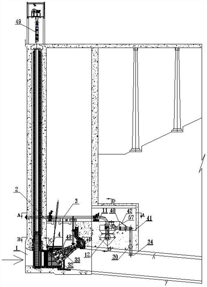
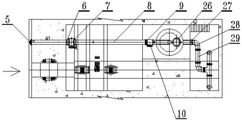
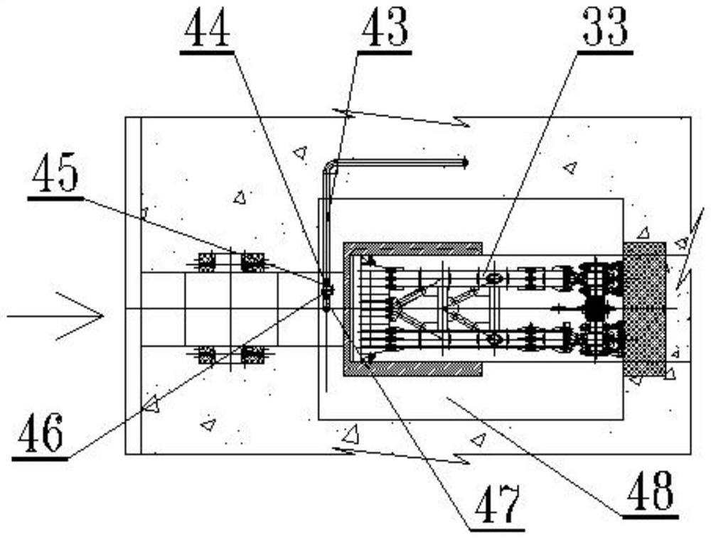
[0059] Example 1. An energy-dissipating and flow-controlling device for discharging ecological flow and filling hydraulic pressure of the gate, the structure of which is as follows: Figure 1-6 , Figure 18 As shown, on one side of the platform 2 of the arc-shaped working gate hoist operator's room at the top of the discharge hole flow channel 1, a main pipeline device 3 for discharging ecological flow and a filling hydraulic pipeline device 4 arranged at the bottom thereof are set.
[0060] The discharge ecological flow main pipeline 3 devices are arranged in sequence along the flow direction of the trash stop device 5, the main pipe before the entrance 6, the accident valve 7, the main pipe after the entrance 8, the expansion joint 9, the working valve 10, the valve outlet elbow 11 and the energy dissipation standpipe device 12 composition;
[0061] After the valve outlet elbow 11 passes through the concrete 13, the lower part is connected with the energy dissipation stand...
Embodiment 2
[0076] Example 2. An energy-dissipating and flow-controlling device for discharging ecological flow and filling hydraulic pressure of the gate, such as Figure 7-12 , Figure 18 shown. The structure of this embodiment is close to Embodiment 1, the difference is:
[0077] On both sides of the arc-shaped working gate hoist operating room platform 2 on the top of the drain hole flow channel 1, the main pipeline device 3 for discharging ecological flow and the filling hydraulic pipeline device 4 arranged at the lower part are arranged symmetrically;
[0078]The stilling shaft 15 is composed of a manhole 22, an upper circular cavity 23, an annular convex body 50 in the middle, and a conical cavity 25 in the lower part;
[0079] The T-shaped frame 37 is welded and fixed to the pre-embedded steel plate 58 arranged on the outside of the annular convex body 50 in the middle;
[0080] The fixed support steel ring 18 of the energy dissipation standpipe device 12 is connected and fixe...
Embodiment 3
[0082] Example 3. An energy-dissipating and flow-controlling device for discharging ecological flow and filling hydraulic pressure of the gate, as shown in the attached figure Figure 13 , Figure 3-6 , Figure 14 , Figure 18 shown. The structure of this embodiment is close to Embodiment 2, the difference is:
[0083] On one side of the arc-shaped work gate hoist operating room platform 2 on the top of the drain hole flow channel 1, the main pipeline device 3 for discharging ecological flow and the filling hydraulic pipeline device 4 arranged at the lower part are arranged symmetrically;
[0084] The stilling shaft 15 is composed of a manhole 22, an upper circular cavity 23, a polygonal annular convex body 24 in the middle, and a conical cavity 25 in the lower part; the polygonal annular convex body 24 in the middle adopts a trapezoidal cross-sectional structure 39; The fixed support steel ring 18 of the standpipe device 12 is connected and fixed into one by bolts 38 thr...
PUM
 Abstract
Description
Claims
Application Information
 - R&D
- Intellectual Property
- Life Sciences
- Materials
- Tech Scout
- Unparalleled Data Quality
- Higher Quality Content
- 60% Fewer Hallucinations
Browse by: Latest US Patents, China's latest patents, Technical Efficacy Thesaurus, Application Domain, Technology Topic, Popular Technical Reports.
© 2025 PatSnap. All rights reserved.Legal|Privacy policy|Modern Slavery Act Transparency Statement|Sitemap|About US| Contact US: help@patsnap.com


