
Drainage pipe ditch device and construction method thereof

A construction method and drainage pipe technology, applied to water supply devices, sewer pipe systems, waterway systems, etc., can solve problems such as complex construction, increased maintenance, water and soil loss, etc., achieve high material utilization, reduce project investment, and increase stability sexual effect

Pending Publication Date: 2022-03-15
SHANGHAI INVESTIGATION DESIGN & RES INST
View PDF0 Cites 0 Cited by
  • Summary
  • Abstract
  • Description
  • Claims
  • Application Information

AI Technical Summary

Problems solved by technology

[0003] In the prior art, most of them use prefabricated concrete drainage ditches or brick drainage ditches on the backfill soil. This kind of drainage ditches need to invest in high labor and material costs in the early stage of construction, and the construction time is long, and the drainage during the application process The ditch is prone to problems such as cracking caused by uneven settlement of backfill soil, which requires frequent maintenance, high maintenance costs, and cannot be reused, resulting in more waste and greater waste; It is open and not easy to cover, so the gutters are often clogged with mud, which adds to the cleaning work, which also damages the gutters during the cleaning process, and adds new repairs
[0004] In order to ensure the uniformity of settlement, the drainage ditch generally needs to be equipped with a sand cushion, which is complicated and expensive.
In the construction site under water and soil conservation, under the condition of rainwater and construction water, soil erosion is usually easy to occur, muddy water enters the drainage ditch and part of the muddy water is discharged to the downstream river or water body, causing new pollution
[0005] In summary, there are many problems in the traditional drainage ditch at present, such as waste of materials, complicated construction, difficult maintenance, etc. Therefore, a new drainage ditch is urgently needed to solve the problems existing in the prior art

Method used


Image

  • Drainage pipe ditch device and construction method thereof
  • Drainage pipe ditch device and construction method thereof
  • Drainage pipe ditch device and construction method thereof

Examples


Embodiment Construction

[0045] The specific implementation manners of the present invention will be described in further detail below in conjunction with the accompanying drawings. These embodiments are only used to illustrate the present invention, not to limit the present invention.

[0046] In the description of the present invention, it should be noted that the terms "center", "longitudinal", "transverse", "upper", "lower", "front", "rear", "left", "right", " The orientations or positional relationships indicated by "vertical", "horizontal", "top", "bottom", "inner", "outer", etc. are based on the orientation or positional relationships shown in the drawings, and are only for the convenience of describing the present invention and simplifying Describes, but does not indicate or imply that the device or element referred to must have a specific orientation, be constructed in a specific orientation, and operate in a specific orientation, and therefore should not be construed as limiting the inventio...


PUM


Abstract

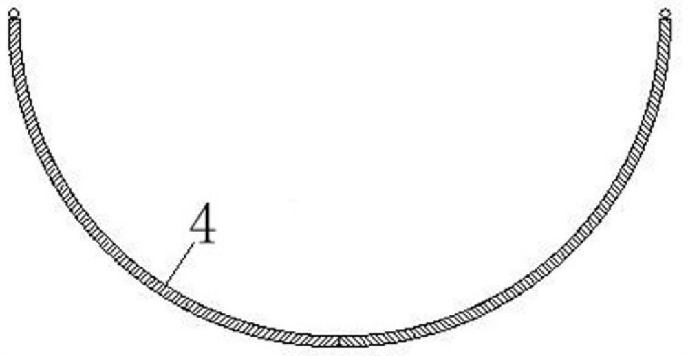
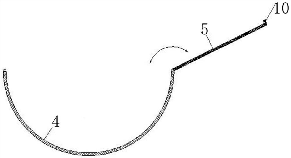
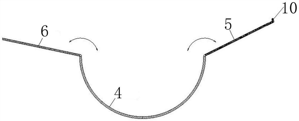
The invention discloses a drainage pipe ditch device and a construction method thereof.The drainage pipe ditch device comprises a drainage pipe ditch section and a socket pipe, one end of the socket pipe sleeves and is fixed to one end of the drainage pipe ditch section, the other end of the socket pipe overhangs outwards to form a socket, and the outer diameter of the drainage pipe ditch section is equal to the inner diameter of the socket pipe; the drainage pipe ditch sections and the socket pipes form drainage pipe ditch units, and a plurality of drainage pipe ditch units are sequentially spliced through corresponding socket ports to form the drainage pipe ditch. The drainage pipe ditch sections and the bell and spigot pipes can be manufactured in a factory and can be universal, the material utilization rate is high, the drainage pipe ditch sections can be long or short according to needs and are convenient to arrange, the adjacent drainage pipe ditch units are spliced through the bell and spigot openings, and construction is convenient; and the drainage pipe ditch device can be recycled, is low-carbon and environment-friendly, and can be maintained in sections in the later period, so that the maintenance cost can be obviously reduced.

Description

technical field [0001] The invention belongs to the technical field of water and soil conservation, and in particular relates to a drainage pipe ditch device and a construction method thereof. Background technique [0002] The drainage ditch is an important part of the rainwater collection system on the construction site. The construction site needs to set up the drainage ditch, but because the drainage ditch is not used for a long time, the drainage ditch is temporary. [0003] In the prior art, most of them use prefabricated concrete drainage ditches or brick drainage ditches on the backfill soil. This kind of drainage ditches need to invest in high labor and material costs in the early stage of construction, and the construction time is long, and the drainage during the application process The ditch is prone to problems such as cracking caused by uneven settlement of backfill soil, which requires frequent maintenance, high maintenance costs, and cannot be reused, resultin...

Claims


Application Information

Patent Timeline
Patent Type & Authority Applications(China)
IPC IPC(8): E03F3/06E03F3/04
CPCE03F3/06E03F3/04Y02A30/60
Inventor 王朝晖桂青陈群李瑶
Owner SHANGHAI INVESTIGATION DESIGN & RES INST
Learn More