Intelligent positioning method and device for impact load

A technology of intelligent positioning and impact load, applied in the field of detection, to achieve the effect of improving solution speed and precision, improving accuracy and high sensitivity

Inactive Publication Date: 2022-03-18
CHINA JILIANG UNIV
View PDF0 Cites 0 Cited by
  • Summary
  • Abstract
  • Description
  • Claims
  • Application Information

AI Technical Summary

Problems solved by technology

[0002] Some equipment needs to know the impact location in time and accurately after receiving the impact, so as to quickly make an assessment and take corresponding countermeasures, such as the impact on the surface of aircraft, high-speed vehicles, etc. With the development of sensing technology, this detection has become a Possibly, but the technology that can use sensors to form a complete detection system is still relatively rare, and the detection accuracy needs to be improved

Method used


Image

  • Intelligent positioning method and device for impact load
  • Intelligent positioning method and device for impact load
  • Intelligent positioning method and device for impact load

Examples


Embodiment 1

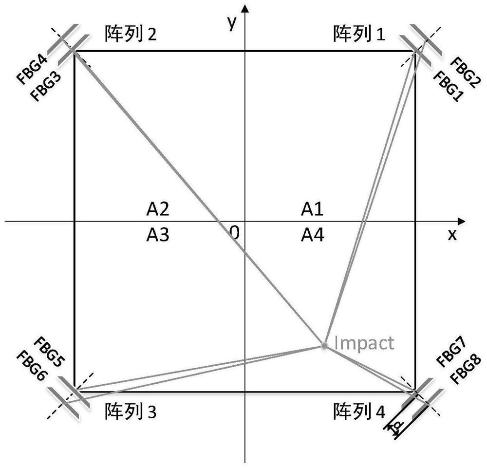
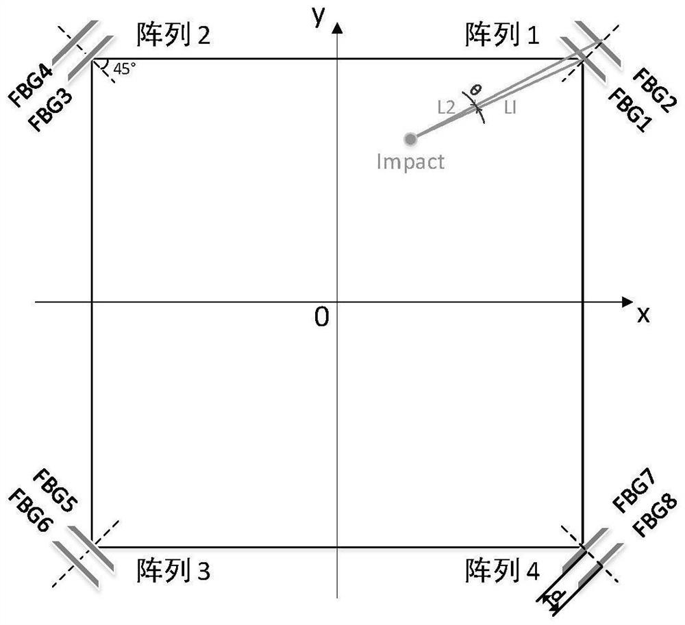
[0033] Such as figure 1 , 2 As shown, an impact load intelligent positioning device includes a sensor array provided in four directions around the impact zone, the present embodiment, the impact of the composite plate, and each direction sensor array includes a relative impact area. Two sensors arranged in the center of radiation, four sensor arrays are located in the same plane. The sensor is the fiber Bragg grating sensor (FBG), and the four sensors arrays are located at four corners of the square, and the fiber Bragg grating sensor is axially opposite the square of the square in the corner point vertically. The angle between the impact is greater than or equal to 45 ° in the stress propagation direction of the composite plate, and the high frequency components in the amplitude frequency characteristics are small.

[0034] The sensor array is J, J = 1, 2, 3, 4; the sensor is FBG I, I = 1, 2, 3, 4, 5, 6, 7, 8. Two FBGs in each set of sensor arrays D.

[0035] Attach the right ang...

Embodiment 2

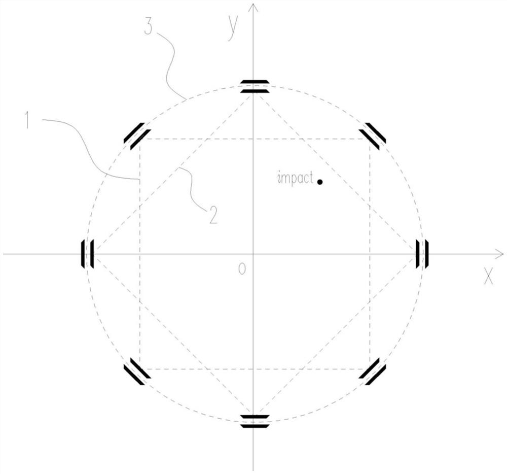
[0103] Such as image 3 As shown, the above-described embodiment is that the four sensor arrays on the square angle point are one detecting unit, and the sensor arrays of the two detecting units are located on the same circumference 3, and the sensor arrays of the two detecting units are arranged at each other. All sensor array spacing, that is, the first detecting unit on the first square 1, and the second detecting unit is on the second square 2.

[0104] The positioning method is that the average value of the position coordinates obtained by the two detecting units serves as the final position coordinate, and since the two detecting units are symmetrical in position, the detection can be achieved. For example, when the impact point is located close to the central portion of a square, it corresponds to the position of the other square, and the structural measurement error of the two has complementarity, whereby the average value of the detection result of the two detection units ...

Embodiment 3

[0108] Such as Figure 4 As shown, in relation to the above-described embodiment, the two detection units located on the same circumference are one detection group, and a plurality of detection groups are provided around the impact zone, and the circumference of the detection group is different, all the circumference of all detection groups. Concentric, the sensor array between different detection groups is equal in circumferential angular intervals, that is, the sensor on different circumferences is not corresponding to the radial direction.

[0109] The average of the position coordinates determined by the multi-group detection group as the final position coordinate. Further, depending on the size of the impact force, the detection value of the different detection group is selected as the final positioning value, for example, when the impact force is large, the detection value of the detection unit on the large circumference is employed. When the impact force is small, the small ...


PUM


Abstract

The invention provides an intelligent positioning method and device for an impact load, and belongs to the technical field of impact positioning. The problem of impact positioning in the prior art is solved. According to the intelligent positioning method and device for the impact load, sensor arrays arranged in four directions around an impact area are included, each direction sensor array comprises two sensors arranged in the outward radiation direction relative to the center of the impact area, and the four sensor arrays are located in the same plane. The shock wave velocities of the two sensors of the sensor array can be approximately the same, so that the number of unknown numbers can be reduced, and the equation set can be solved. The included angle between the axial direction of the sensor and the shock wave propagation direction is larger than or equal to 45 degrees, at the moment, the sensitivity of the fiber bragg grating sensor is high, meanwhile, high-frequency components in amplitude-frequency characteristics are few, and detection of the sensor is facilitated. The detection precision is improved by eliminating the sensor array with the largest included angle with the impact source.

Description

Technical field [0001] The present invention belongs to the field of detection, particularly an impact positioning technique. Background technique [0002] Some devices need timely and accurately know the impact position after receiving the impact, so as to quickly make an assessment and adopt a corresponding response strategy, such as the impact of the aircraft, high-speed vehicles, and the development of sensing technology, this test has become It is possible, but the technology that can be used to form a full detection system is still relatively rare, and the accuracy of detection is more improved. Inventive content [0003] It is an object of the present invention to provide an intelligent positioning method and apparatus of an impact load, an intelligent positioning method, and apparatus of the impact load, and a device capable of impact loading. [0004] It is achieved by the following technical solutions: an intelligent positioning device of an impact load comprising a se...

Claims


Application Information

Patent Timeline
Patent Type & Authority Applications(China)
IPC IPC(8): G01S5/16G01C21/20
CPCG01S5/16G01C21/20
Inventor 江文松杜亮娅罗哉杨力郭斌
Owner CHINA JILIANG UNIV
Why Eureka
Try Eureka