Preparation method of composite current collector
A current collector and coating technology, which is applied in the direction of electrode carrier/current collector, electrical components, battery electrodes, etc., can solve the problem that the conductor layers on both sides of the composite current collector are difficult to achieve conduction, so as to improve the production efficiency and reduce the difficulty of the process , The effect of reducing the internal resistance of the battery
- Summary
- Abstract
- Description
- Claims
- Application Information
AI Technical Summary
Problems solved by technology
Method used
Image
Examples
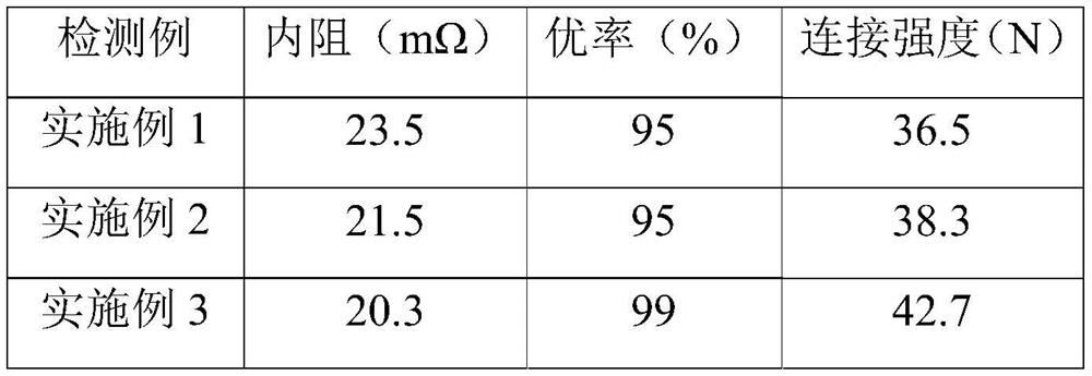
Embodiment 1
[0026] A preparation method of a composite current collector, specifically comprising the following steps:
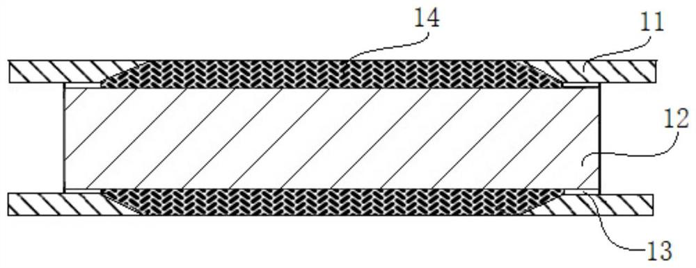
[0027] (1), select polyethylene terephthalate as the insulating support layer, and coat a layer of metal aluminum coating with a thickness of 1 μm on both sides of the insulating support layer by vacuum evaporation, and each layer of metal aluminum coating is uniform. It includes a plurality of coating areas 01, and a blank area 02 is left between two adjacent coating areas 01 (see figure 1 ), and then the insulating supporting layer after coating is cut, and each insulating supporting layer after cutting includes a corresponding coating area 01 on its two sides, and the coating area 01 of each insulating supporting layer after cutting is There are blank areas 02 on both sides, that is, the plating area 01 on each insulating support layer is located between the blank areas 02 on both sides;
[0028] (2), see figure 2 The inner end of the aluminum foil 11 with a trape...
Embodiment 2
[0031] A preparation method of a composite current collector, specifically comprising the following steps:
[0032] (1), choose polyethylene terephthalate as the insulating support layer, and coat a layer of metal aluminum coating with a thickness of 1.1 μm on both sides of the insulating support layer by vacuum evaporation, and each layer of metal aluminum coating Each includes a plurality of coating areas 01, and a blank area 02 is left between two adjacent coating areas 01 (see figure 1 ), and then the insulating supporting layer after coating is cut, and each insulating supporting layer after cutting includes a corresponding coating area 01 on its two sides, and the coating area 01 of each insulating supporting layer after cutting is There are blank areas 02 on both sides, that is, the plating area 01 on each insulating support layer is located between the blank areas 02 on both sides;
[0033] (2), see figure 2 The inner end of the aluminum foil 11 with a trapezoidal l...
Embodiment 3
[0036] A preparation method of a composite current collector, specifically comprising the following steps:
[0037] (1), choose polyethylene terephthalate as the insulating support layer, and coat a layer of metal aluminum coating with a thickness of 1.2 μm on both sides of the insulating support layer by vacuum evaporation, and each layer of metal aluminum coating Each includes a plurality of coating areas 01, and a blank area 02 is left between two adjacent coating areas 01 (see figure 1 ), and then the insulating supporting layer after coating is cut, and each insulating supporting layer after cutting includes a corresponding coating area 01 on its two sides, and the coating area 01 of each insulating supporting layer after cutting is There are blank areas 02 on both sides, that is, the plating area 01 on each insulating support layer is located between the blank areas 02 on both sides;
[0038] (2), see figure 2 The inner end of the aluminum foil 11 with a trapezoidal l...
PUM
| Property | Measurement | Unit |
|---|---|---|
| thickness | aaaaa | aaaaa |
| thickness | aaaaa | aaaaa |
| thickness | aaaaa | aaaaa |
Abstract
Description
Claims
Application Information
 - R&D
- Intellectual Property
- Life Sciences
- Materials
- Tech Scout
- Unparalleled Data Quality
- Higher Quality Content
- 60% Fewer Hallucinations
Browse by: Latest US Patents, China's latest patents, Technical Efficacy Thesaurus, Application Domain, Technology Topic, Popular Technical Reports.
© 2025 PatSnap. All rights reserved.Legal|Privacy policy|Modern Slavery Act Transparency Statement|Sitemap|About US| Contact US: help@patsnap.com


