Angle adjusting device and self-danger-avoiding type sun-tracking solar power generation equipment

An angle adjustment device and an angle adjustment technology, applied in the field of solar power generation, can solve the problems of solar panel blowing, damage or even scrapping, high production cost, poor linkage adjustment accuracy and stability, etc., to improve solar power generation power, production and assembly. Low cost and smooth angle adjustment

Active Publication Date: 2022-03-18
ZHUHAI CHENGDIAN TECH CO LTD
View PDF7 Cites 0 Cited by
  • Summary
  • Abstract
  • Description
  • Claims
  • Application Information

AI Technical Summary

Problems solved by technology

[0003] However, with the continuous improvement of technical requirements and higher requirements for use, the existing sun-tracking solar power generation equipment has gradually revealed its new technical problems in practical applications: 1. The existing solar power generation equipment is fixed installation, generally The corrugated steel structure is used. At present, some of the rich functions are based on the original power generation equipment structure, only adding the sun tracking function of horizontal rotation, and do not have the function of synchronous adjustment of horizontal angle and pitch angle. The sun’s optimal irradiation angle and the utilization rate of solar energy still need to be further improved, and the linkage mode and structure of the angle adjustment mechanism applied to solar power generation equipment in the early stage are relatively complicated, and the overall production cost is high. , leading to poor accuracy and stability of linkage adjustment; 2. The solar photovoltaic panels in the existing solar power generation equipment are all spliced ​​and assembled by several small solar panels to form a complete solar panel, and are fixed on the bracket by fixed installation. The surface of the finished solar panel is square, rectangular or circular. In order to obtain a larger illuminated area, the surface area of ​​the solar panel after assembly is generally larger. , The labor intensity of the operator is very high, the cost of installation and maintenance is high, the construction volume is large, and there are certain safety hazards. At the same time, because the solar panel is a fragile object, it is easy to cause damage to the solar panel during the splicing and assembly process.
3. As we all know, solar power generation equipment is usually installed in open areas with sufficient sunlight, and natural weather and meteorological changes occur from time to time. The fixed installation method cannot avoid or avoid the dangers and injuries caused by bad weather as much as possible. If you cannot avoid danger, you can only let the wind and rain blow. Board blown off, damaged or even scrapped. On the other hand, it also accelerates the aging of solar power generation equipment, resulting in rapid attenuation of power generation and short service life of the equipment.
4. Since the solar power generation equipment is installed in the field area, it will inevitably produce the deposition of dust and gravel. If it is deposited for a long time, a certain thickness of deposition layer will be produced to cover the surface of the solar panel. If it is not cleaned, it will inevitably cause power generation. The power is greatly attenuated, which affects the power generation efficiency. In order to deal with this situation, the existing solar equipment usually uses manual cleaning work on a regular basis, which is labor-intensive and labor-intensive. At present, the conventional method is to use a robot cleaning device to add robot cleaning to the power generation equipment. The device greatly increases the complexity of the equipment structure, and also greatly increases the cost of equipment development and production.
[0004] In summary, the existing solar power generation equipment has low solar energy utilization rate, low angle adjustment accuracy and stability in current practical applications, and the production, installation and maintenance costs of the whole machine are high, the construction volume is large, and the use process is safe. Technical defects such as relatively low level, inability to avoid danger, fast decay of power generation, short service life, and high cleaning cost

Method used


Image

  • Angle adjusting device and self-danger-avoiding type sun-tracking solar power generation equipment
  • Angle adjusting device and self-danger-avoiding type sun-tracking solar power generation equipment
  • Angle adjusting device and self-danger-avoiding type sun-tracking solar power generation equipment

Examples


Embodiment 1

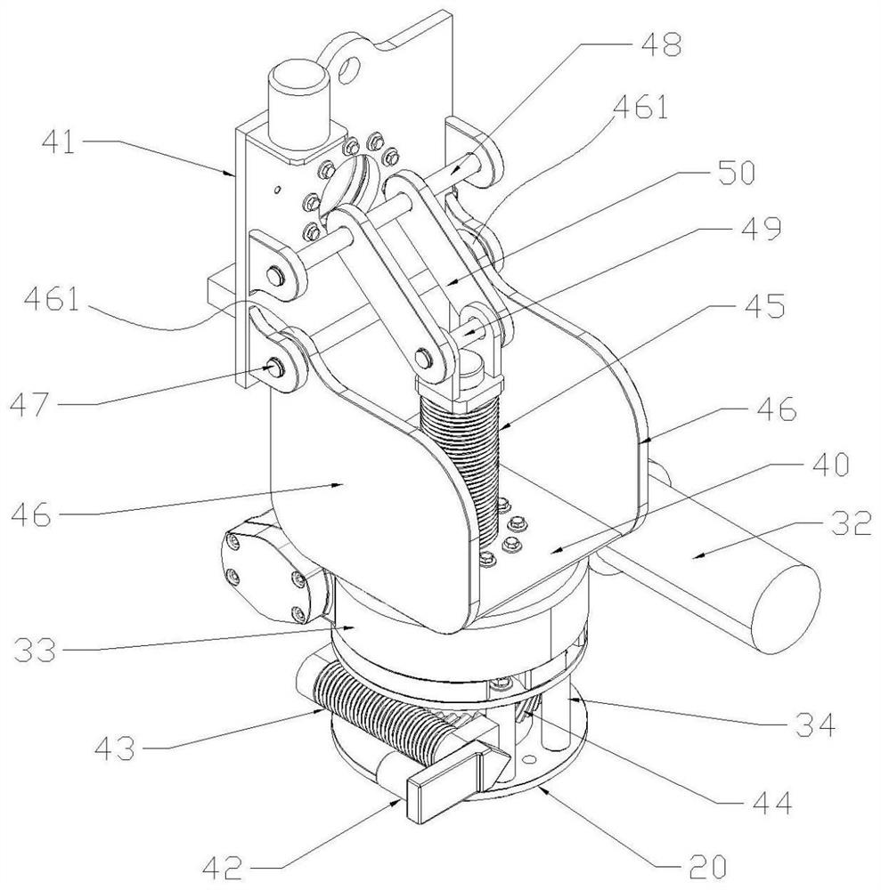
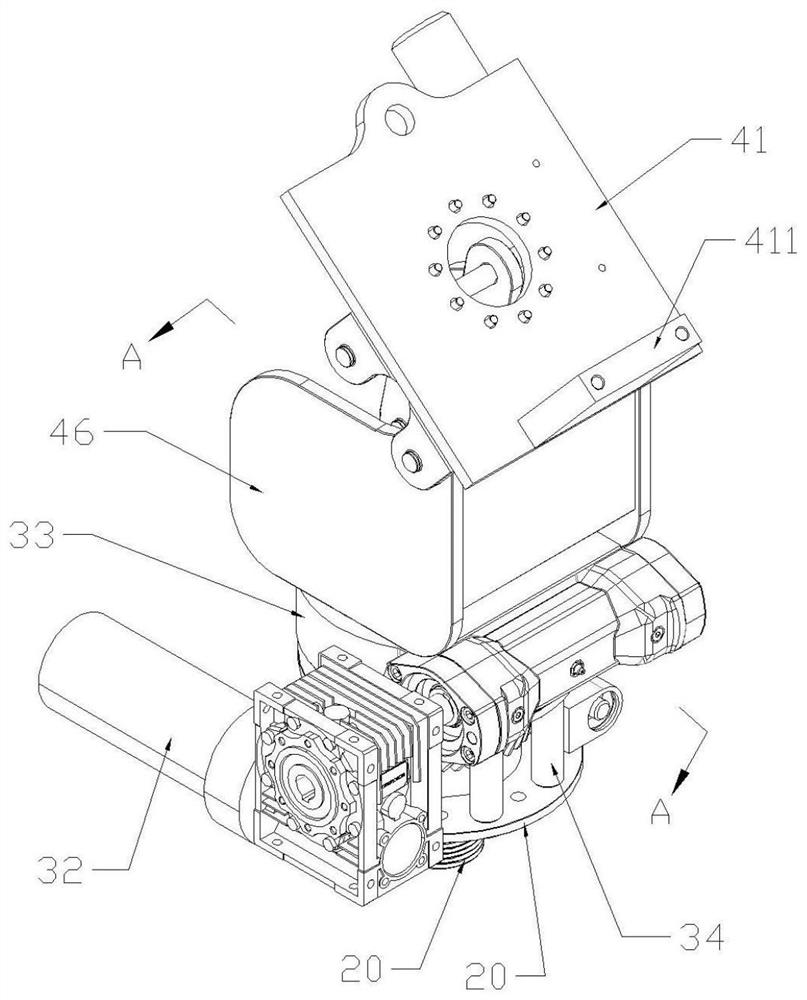
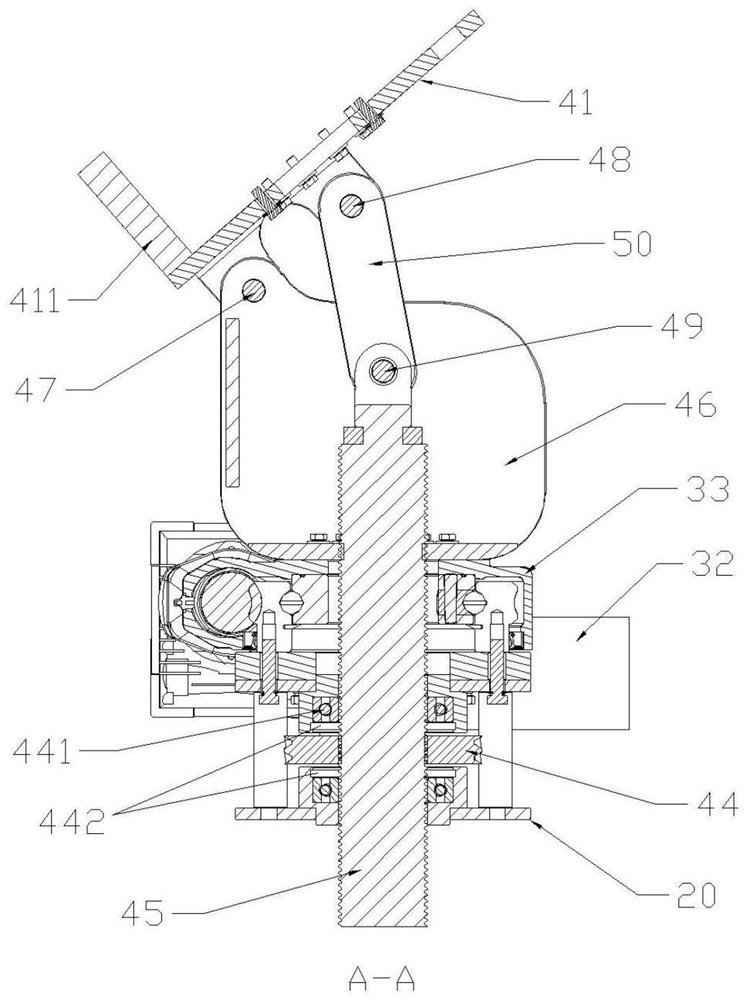
[0045] Such as Figure 1-4 As shown, the angle adjustment device of the present invention includes a base 20, a horizontal angle adjustment assembly, and a pitch angle adjustment assembly. The base 20 is provided with a number of support columns 34, and the horizontal angle adjustment assembly includes a transmission-connected horizontal Motor 32, rotary reducer 33, the horizontal motor 32 is electrically connected with the external control system 21, the lower part of the rotary reducer 33 is fixedly installed on the support column 34, and the horizontal angle adjustment assembly is powered by the horizontal motor 32, which can be adjusted left and right. Turn to achieve angle adjustment in the horizontal direction;

[0046] The pitch angle adjustment assembly includes a fixed plate 40, a mounting plate 41, and a pitch motor 42, a short worm 43, a double-sided gear 44, and a long worm 45 that are sequentially connected by transmission. The pitch motor 42 is electrically conne...

Embodiment 2

[0050] Such as Figure 5-Figure 12 As shown, in this implementation, the self-avoiding sun-tracking solar power generation equipment includes a frame 1 and a blade retracting device. The bottom of the frame 1 is symmetrically provided with a number of mounting holes 11, and the device is installed through the mounting holes 11 by bolts. Install and fix at the finger position. The installation of the equipment does not require cumbersome construction preparations. It is only necessary to pre-embed the bolts at the installation position in advance, then hoist the solar power generation equipment to the bolt position, align the installation holes 11, and then tighten the nuts to complete the installation. And fixed, the equipment can be put into use. According to the geology of different installation sites, installation methods include but are not limited to expansion bolts, pre-embedded cement foundations, screw piles, etc. A control system 21, an inverter 22 electrically conne...

Embodiment 3

[0059] Such as Figure 10 , Figure 11 As shown, in this embodiment, at least one cleaning brush 621 is provided on the back of the bracket 62, and the cleaning brush 621 on the back of the bracket 62 at the front end is in contact with the surface of the solar photovoltaic panel 64 at the rear end. , in order to achieve a better cleaning effect in practical applications, preferably two cleaning brushes 621 are provided. At each sunrise and sunset time node control system 21 of the power generation equipment will control the blade retracting device to expand and retract the solar blade 6. During each expansion and retraction process, the solar blade 6 will perform relative movement, and at the same time the support The cleaning brush 621 on the back of the 62 will clean the panel 63 and the solar photovoltaic panel 64 of the solar blade 6 . At the same time, the panel 63 adopts easy-to-clean glass to improve cleaning efficiency.

[0060] Such as Figure 15 As shown, in thi...


PUM


Abstract

The invention relates to an angle adjusting device and self-risk-avoiding type sun-tracking solar power generation equipment. The angle adjusting device comprises a base, a horizontal angle adjusting assembly, a pitching angle adjusting assembly and a mounting plate, the mounting plate is used for mounting a solar power generation component, and the angles of the mounting plate in the horizontal direction and the pitching direction can be adjusted through the horizontal angle adjusting assembly and the pitching angle adjusting assembly. The solar power generation component can carry out photovoltaic power generation work at the optimal direct sunlight angle, and the solar energy utilization rate and the power generation efficiency are effectively improved. The self-danger-avoiding type sun-tracking solar power generation equipment comprises the angle adjusting device and the blade unfolding device, the solar blades are controlled to be unfolded or folded through the blade unfolding device, the equipment can keep the best direct sunlight angle from sunrise to sunset all the time, and when severe weather such as strong wind, rain and snow is encountered, the sun-tracking solar power generation equipment can be used for sun tracking. The solar blades can be folded at the first time, and the damage probability is reduced. The invention can be widely applied to the field of solar power generation.

Description

technical field [0001] The invention relates to the technical field of solar power generation, in particular to an angle adjustment device and self-risk-avoiding sun-tracking solar power generation equipment including the angle adjustment device. Background technique [0002] Solar photovoltaic power generation is a direct power generation that uses solar-grade semiconductor electronic devices to effectively absorb solar radiation energy and convert it into electrical energy. With continuous application and development, the technology of solar photovoltaic power generation has been continuously broken through and matured. As we all know, solar photovoltaic power generation requires sunlight to generate electricity, and the angle and position of the sun's radiation are constantly changing. Only by prolonging the duration of sunlight can we make full use of solar energy and improve power generation efficiency. The equipment emerges as the times require. In the control system o...

Claims


Application Information

Patent Timeline
IPC IPC(8): H02S20/32H02S30/20H02S40/10F24S30/45F24S50/20
CPCH02S20/32H02S30/20H02S40/10F24S30/45F24S50/20Y02E10/47Y02E10/50
Inventor 余洋谢志刚黄日富曾飞
Owner ZHUHAI CHENGDIAN TECH CO LTD
Why Eureka
Try Eureka