Negative electrode, secondary battery, and solid-state secondary battery
A negative electrode and negative active material technology, applied in the fields of machines, processes, products or compositions, can solve problems such as operating temperature range, fire, liquid leakage, etc.
- Summary
- Abstract
- Description
- Claims
- Application Information
AI Technical Summary
Problems solved by technology
Method used
Image

Examples
Embodiment approach 1
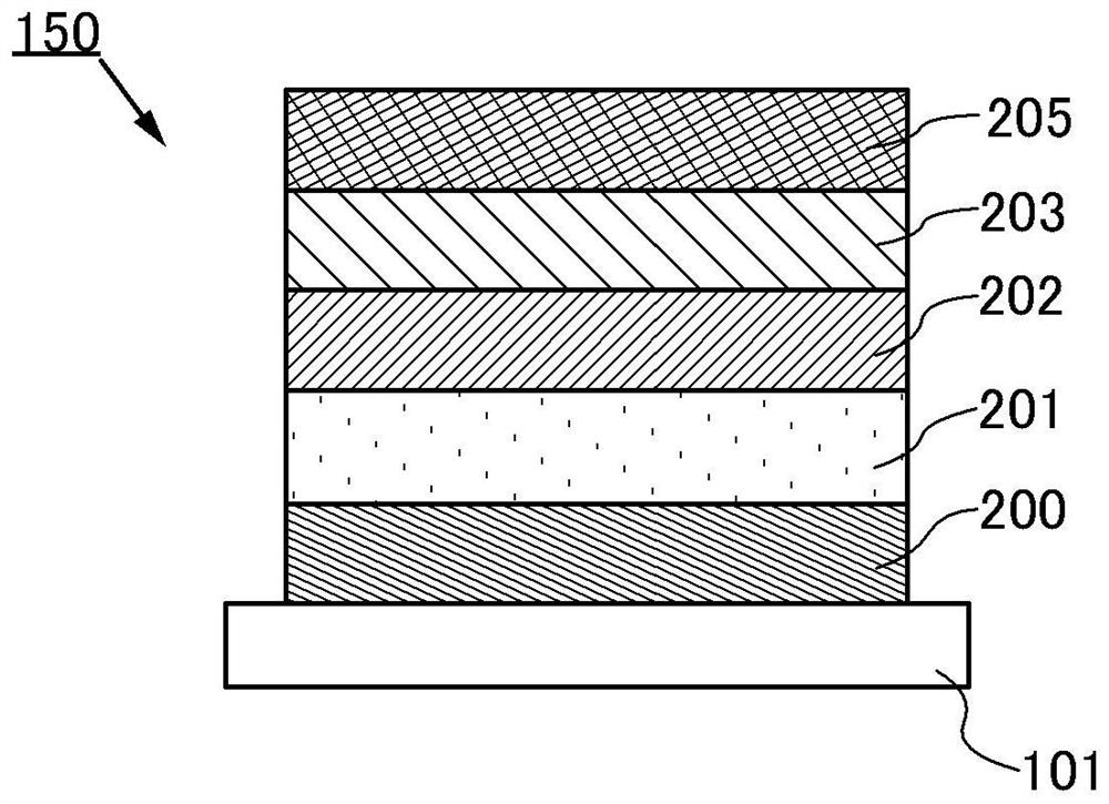
[0058] Refer Figure 1A , Figure 2A and Figure 2b A negative electrode and a secondary battery will be described in the present invention. In the present specification, the negative electrode includes at least a negative electrode fluid and an anode active material layer.
[0059] exist Figure 1A In the secondary battery 150 shown in one embodiment of the present invention, a negative electrode concentration fluid layer 200, a negative electrode active material layer 201, a solid electrolyte layer 202, a positive electrode active material layer 203 are sequentially laminated, and the positive electrode fluid layer 205 is laminated. . Note that the laminate sequence can also be reversed. That is, the positive electrode collector layer 205, the positive electrode active material layer 203, the solid electrolyte layer 202, the negative electrode active material layer 201, and the negative electrode concentration fluid layer 200 are sequentially laminated on the substrate 101.
[0060]...
Embodiment approach 2
[0099] In the present embodiment, a method of manufacturing a solid secondary battery in the first embodiment will be described. in addition, Figure 5 Show it Figure 4A and Figure 4b An example of a manufacturing process of the structure shown.
[0100] First, the negative electrode concentration fluid layer 200 is formed on the substrate. As a deposition method, a sputtering method, a vapor deposition method, and the like can be used. Alternatively, a substrate having conductivity can be used as a concentration fluid. The above materials can be used as the negative electrode current fluid layer. The thickness of the negative electrode concentration fluid layer 200 is preferably 5 μm or more and 100 μm or less, preferably 5 μm or more and 30 μm.
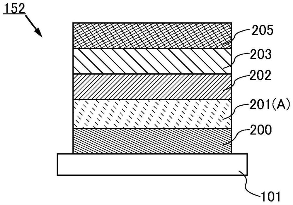
[0101] The first layer of negative active material layer 201 (a) is then deposited. Note that the first layer negative electrode active material layer 201 (1) is shown in the drawings. The negative electrode active material layer 201 (a)...
Embodiment approach 3
[0115] In the present embodiment, an example of a material that can be used to include a secondary battery of the present invention will be described. In the present embodiment, the negative electrode and the electrolyte of the present invention are described as an example in the secondary battery surrounded by the positive electrode.
[0116] [positive electrode]
[0117] The positive electrode includes a positive electrode active material layer and a positive electrode concentration fluid layer.
[0118]
[0119] The positive electrode active material layer can include a positive electrode active material film or a positive electrode active material particle. In the case of including a positive electrode active material film, a thin film battery can be formed by a combination of a negative electrode according to the present invention, which is preferred. On the other hand, by including a positive electrode active material particles, a large capacity of the positive electrode ca...
PUM
| Property | Measurement | Unit |
|---|---|---|
| thickness | aaaaa | aaaaa |
| thickness | aaaaa | aaaaa |
| thickness | aaaaa | aaaaa |
Abstract
Description
Claims
Application Information
 - R&D
- Intellectual Property
- Life Sciences
- Materials
- Tech Scout
- Unparalleled Data Quality
- Higher Quality Content
- 60% Fewer Hallucinations
Browse by: Latest US Patents, China's latest patents, Technical Efficacy Thesaurus, Application Domain, Technology Topic, Popular Technical Reports.
© 2025 PatSnap. All rights reserved.Legal|Privacy policy|Modern Slavery Act Transparency Statement|Sitemap|About US| Contact US: help@patsnap.com