Magnetic powder mixing device

A material mixing device and magnetic powder technology, applied in mixers, transportation and packaging, shaking/oscillating/vibrating mixers, etc., can solve the problems of easy accumulation in the material tank, affecting the mixing effect, and inconvenient cleaning of the material tank, etc., to achieve Improve the use effect, improve the stirring effect, the effect of simple structure

Pending Publication Date: 2022-03-22
温州欣东磁业有限公司
View PDF0 Cites 0 Cited by
  • Summary
  • Abstract
  • Description
  • Claims
  • Application Information

AI Technical Summary

Problems solved by technology

[0002] The production and processing of magnets usually needs to be realized through the following steps, which usually include steps such as batching, smelting ingot making, powder making, pressing, sintering and tempering, magnetic detection, grinding, pin cutting, electroplating, and magnetization. , in addition to obtaining iron-cobalt-nickel magnetic powder through the jet mill, these magnetic powders also need to be mixed. At present, the magnetic powder is mainly mixed by a mixer, but because the magnetic powder contains different types of magnetic powder, due to the difference in individual properties, there are In the case of uneven mixing, at the same time, because the magnetic powder is relatively fine, it is easy to adhere to the inner wall of the material tank, which affects the mixing effect and the proportioning effect, and makes it inconvenient to clean the subsequent material tank, and it is easy to accumulate in the material tank after long-term adhesion

Method used


Image

  • Magnetic powder mixing device
  • Magnetic powder mixing device
  • Magnetic powder mixing device

Examples


Embodiment Construction

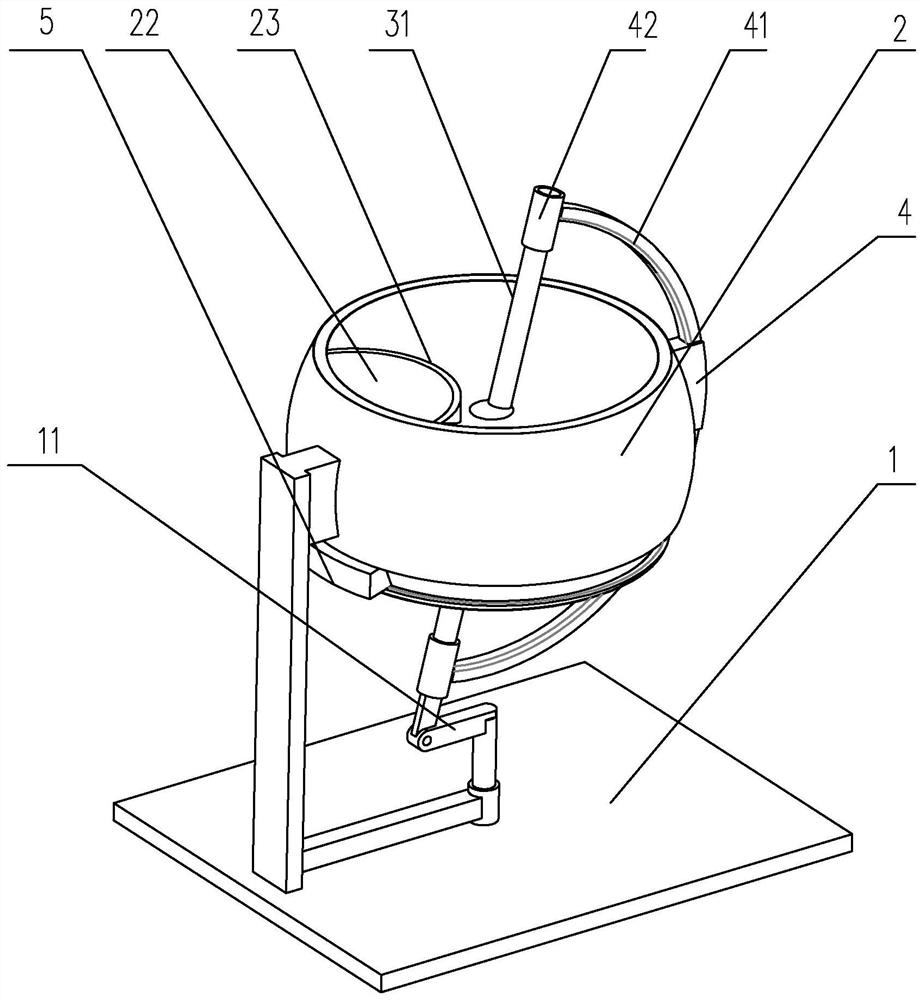
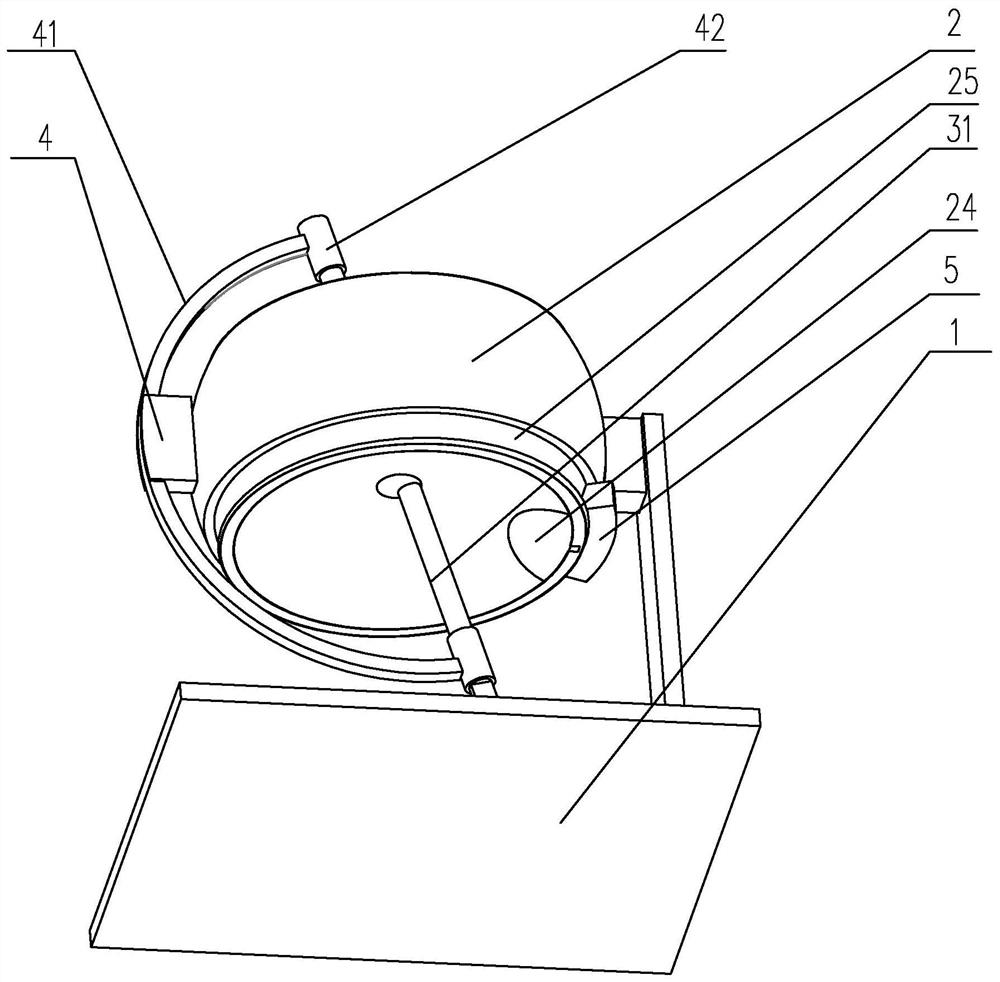
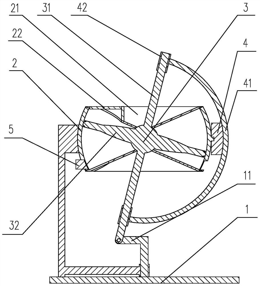
[0024] Examples of the magnetic powder mixing device of the present invention are Figure 1 to Figure 4 Shown: includes a frame body 1, the frame body 1 is provided with a stirring tank 2, the upper and lower ends of the stirring tank 2 are respectively formed with arc-shaped concave cavities 21, and the stirring tank 2 is located between the two arc-shaped concave cavities 21 There is a connection ball 3 between them, and the connection ball 3 is respectively connected to the two arc-shaped concave cavities 21. The connection ball 3 is partially exposed outside the stirring tank 2, and the connection ball 3 is exposed to the stirring tank. 2, a transmission rod 31 is extended on the outer part, and the transmission rod 31 is arranged obliquely. The frame body 1 is provided with a swing rod 11 and a driving member for driving the swing rod 11 to rotate. One end of the swing rod 11 is connected to the drive The output end of the piece is connected, and the other end is rotation...


PUM


Abstract

The invention discloses a magnetic powder mixing device which comprises a frame body, a stirring tank is arranged on the frame body, arc-shaped concave cavities are formed in the upper end and the lower end of the stirring tank respectively, a connecting ball head is arranged at the position, between the two arc-shaped concave cavities, of the stirring tank, and the connecting ball head is rotationally connected with the two arc-shaped concave cavities respectively. The portion, exposed out of the stirring tank, of the connecting ball head extends to form a transmission rod, the transmission rod is obliquely arranged, a swing rod and a driving part are arranged on the frame body, one end of the swing rod is connected with the output end of the driving part, the other end of the swing rod is rotationally connected with the swing rod, and the connecting ball head extends towards the inner wall of the stirring tank to form an annular flange. An electromagnet is arranged on the edge of the annular flange, a plurality of through holes are further formed in the annular flange, and the radian of the inner wall of the stirring tank is matched with the motion trail of the edge of the annular flange. The magnetic powder mixing device is simple in structure and has a better magnetic powder mixing effect, meanwhile, adhesion of magnetic powder to the edge of the material barrel is reduced, and the using effect of the overall structure is improved.

Description

technical field [0001] The invention relates to the technical field of magnet processing equipment, in particular to a magnetic powder mixing device. Background technique [0002] The production and processing of magnets usually needs to be realized through the following steps, which usually include steps such as batching, smelting ingot making, powder making, pressing, sintering and tempering, magnetic detection, grinding, pin cutting, electroplating, and magnetization. , in addition to obtaining iron-cobalt-nickel magnetic powder through the jet mill, these magnetic powders also need to be mixed. At present, the magnetic powder is mainly mixed by a mixer, but because the magnetic powder contains different types of magnetic powder, due to the difference in individual properties, there are In the case of uneven mixing, at the same time, because the magnetic powder is relatively fine, it is easy to adhere to the inner wall of the material tank, which affects the mixing effect...

Claims


Application Information

Patent Timeline
Patent Type & Authority Applications(China)
IPC IPC(8): B01F31/40B01F35/12
Inventor 黄直秀李永胜
Owner 温州欣东磁业有限公司
Why Eureka
Try Eureka