Novel spraying system

A new type of ball valve technology, applied in the field of coatings, can solve the problems of increased working hours, uncontrollable gas content, and small spraying area

Pending Publication Date: 2022-03-22
YUTAKA ELECTRONICS SH
View PDF1 Cites 0 Cited by
  • Summary
  • Abstract
  • Description
  • Claims
  • Application Information

AI Technical Summary

Problems solved by technology

[0003] For example, a waste material recycling system disclosed in a Chinese patent (authorized notification number is CN108504982A), although it solves the problem of uncontrollable gas content in the process of target rotary spraying, ensures the stability and consistency of the workpiece during the sputtering coating process. The gas content in the workpiece meets the production requirements, so as to obtain a sputtering coating target with high spraying quality, but it does not solve the problem of low spraying efficiency and small spraying area, which greatly increases the entire working hours.

Method used


Image

  • Novel spraying system

Examples


Embodiment 1

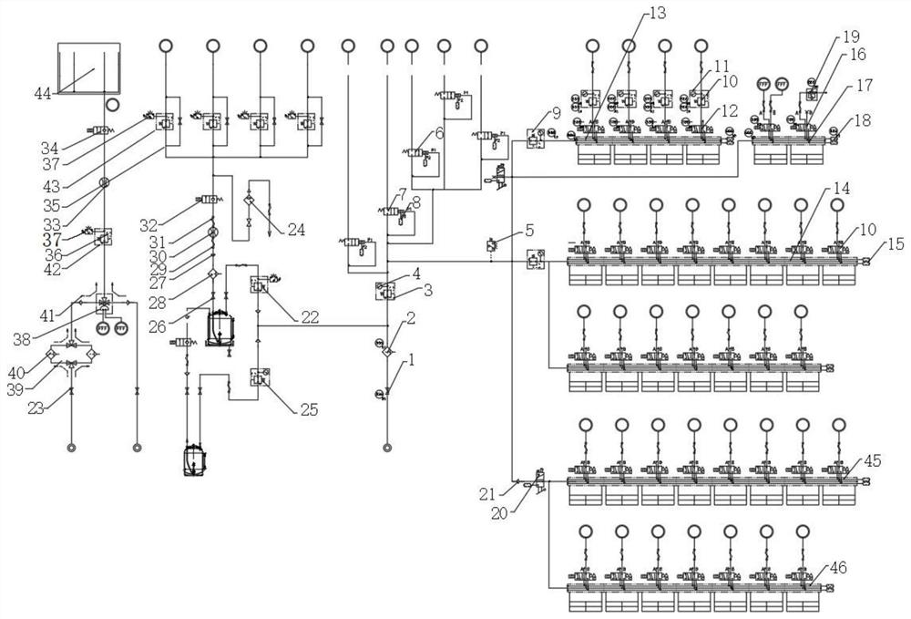
[0030] See figure 1 As shown, a technical solution provided by the present invention: a novel spraying system, the novel spraying system including a blow box 44, and the output port of the input box 44 is fixedly coupled with a sixth electromagnetic valve 34, and the sixth electromagnetic valve 34. On one side, a second flow meter 33 is provided, and one side of the second flow meter 33 is provided with a sixth pressure pressure valve 36 having a valve block 42 on one side of the sixth pressure regulating valve 36, the first The other side of the six-regulating valve 36 is provided with a second pressure switch 37, which is electrically connected to the sixth pressure reducing valve 36; a ball valve assembly, the ball valve assembly including a first ball valve 23. The third ball valve 38, the second single-directional valve 41 and the filter 40, the third ball valve 38 is disposed on one side of the sixth pressure valve 36, and the two sides of the third ball valve 38 have a firs...

Embodiment 2

[0032]A new spray system, the novel spraying system further includes a fifth pressure roller 43, and the fifth pressure roller 43 communicates with the outer conduit, and the second pressure switch 37 is provided on one side of the fifth pressure regulating valve 43. The second pressure switch 37 is coupled to the fifth pressure roller 43, and the side of the fifth modifier is provided with a variable diameter inner wire 35, and the function of the fifth pressure regulating valve 43 can be controlled. The coating input is induced to protect the internal equipment of the system, while the fifth pressure roller 43, the variable-diameter inner wire 35 and the second pressure switch 37 constitute a restriction assembly, limiting the amount of external coating, and restriction assembly can be based on It is necessary to determine the number, and the side of the variable interpolation port 35 is provided with a fifth solenoid valve 32, and a shockproof rubber 31 is provided on one side ...


PUM


Abstract

The invention relates to the technical field of coatings, in particular to a novel spraying system which comprises an input box, an output port of the input box is fixedly connected with a sixth electromagnetic valve, a second flow meter is arranged on one side of the sixth electromagnetic valve, a sixth pressure regulating valve is arranged on one side of the second flow meter, and a valve block is arranged on one side of the sixth pressure regulating valve. The device has the beneficial effects that through the action of a sixth electromagnetic valve, paint fed into a feeding box from the outside can be conveyed into the whole system for use, through the action of a second flow meter, the amount of the paint conveyed into the system is metered, statistics is facilitated, the phenomenon of excessive feeding is prevented, and through the action of a sixth pressure regulating valve, the paint can be conveniently fed into the system. The circulating speed of the real coating in the system is controlled, the situation that the coating flows back is prevented through the effect of a second one-way valve, and it is guaranteed that the coating in the system does not exceed the bearable range of the system through the effect of a third filter.

Description

Technical field [0001] The present invention relates to the field of coating materials, specific for a new spray system. Background technique [0002] Spraying through the spray gun or disc atomizer, is dispersed into a coating method of the surface of the coated surface by means of a spray gun or dish atomizer. Various derivatives can be divided into air spray, no air spray, electrostatic spray, and the above-mentioned basic sprayed form, such as high flow low pressure atomized spray, thermal spraying, automatic spraying, multi-group spraying, etc., however, various various There are still problems in the sample spray device. [0003] As disclosed in China Patent (Authorized Number CN108504982A), a waste recovery system disclosed, although it achieves the problem that the gas content cannot be controlled in the rotary spraying process of the target, ensuring the stability and consistency of workpiece during the sputter coating. Sex, the gas content in the workpiece meets the pro...

Claims


Application Information

Patent Timeline
Patent Type & Authority Applications(China)
IPC IPC(8): B05B12/08
CPCB05B12/08
Inventor 张杨
Owner YUTAKA ELECTRONICS SH
Why Eureka
Try Eureka