Damp-proof device for equipment in machine room

An equipment and equipment room technology, applied in the field of equipment moisture-proof devices in equipment rooms, can solve problems such as equipment corrosion and damage

Inactive Publication Date: 2022-03-22
安徽美诺克智能科技有限公司
View PDF1 Cites 0 Cited by
  • Summary
  • Abstract
  • Description
  • Claims
  • Application Information

AI Technical Summary

Problems solved by technology

[0004] In the current existing technology, the vents set in the computer room are generally open. In this way, when the computer room is used outdoors, the humid air from the outside will enter the interior of the computer room through the vents when it rains, which will cause corrosion and damage to the internal equipment in the long run.

Method used


Image

  • Damp-proof device for equipment in machine room
  • Damp-proof device for equipment in machine room
  • Damp-proof device for equipment in machine room

Examples


Embodiment 1

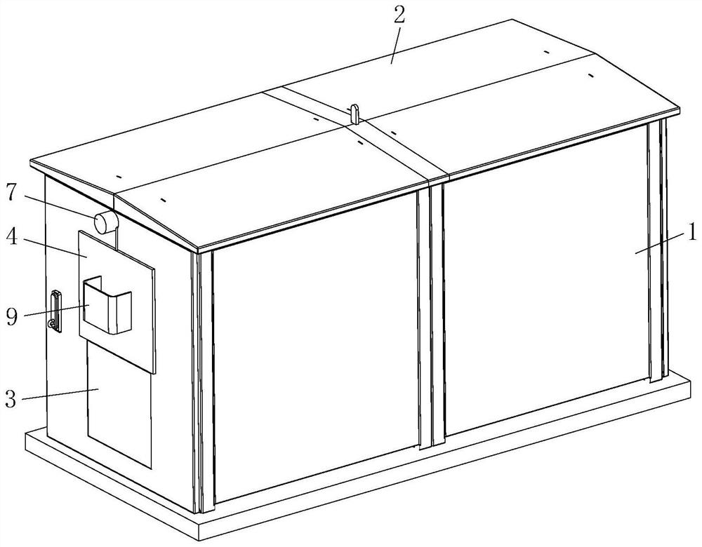
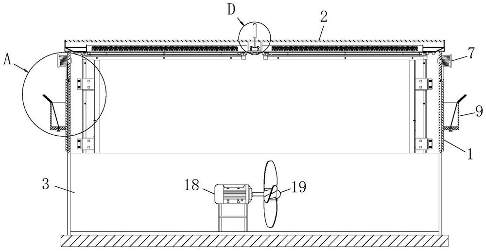
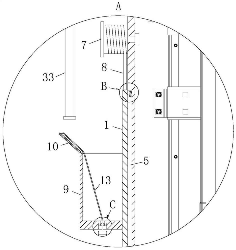
[0032] Such as Figure 1 to 5As shown in a moisture-proof room equipment apparatus according to the present invention, comprises a body 1 housing; the housing body 1 is attached to the top plate 2; 1 on both sides of the housing body 3 defines a vent; the vents the upper movable plate 43 is provided; position close to the housing body 1 of the movable plate 4 defines a chute 5; 5 slidably connected to the slider chute 6, 6 and the slider 4 and the movable plate solid bonding; the housing 4 above the movable plate 1 is rotated by a torsion spring connected to reel 7; 7 on the reel and fixed to the connection cord 8 is wound One, One and the other end connected to the rope 8 activity plate 4 is fixed; the movable plate 4 is fixed to the outer water tank 9, and a water tank 9 is provided with leakage component; when it rains, rain water into the collection tank 9, a greater force of gravity, slide down the drive plate 4 3 and the automatic vent sealing to prevent moist air through a v...

Embodiment 2

[0042] Such as Figure 8 As shown in Comparative Example a, wherein another embodiment of the present invention are: the catheter 27 has elasticity, and the catheter 27 away from the curved section of the electrical contact sheet 23 is curved coiled; by conduit 27 to a curved coiled, resilient conduit 27 can be increased, so that the arcuate link 21 is driven by the rotation of the electric contact 23, not to be bound by a conduit 27, to ensure the smooth operation of the rotation.

[0043] Working principle: when it rains, rain water into the collection tank 9, a greater force of gravity, slide down the drive plate 4 and the self-sealing vents 3, to avoid moist air through a vent into the interior of the engine room 3, storm after the rain water tank 9 from leaking through the leak down assembly, the reel 7 is rotated and the connection cord One effect of the torsion spring 8 in the retractor, and then pull on the move the movable plate 4, so that the engine room through a natural...


PUM


Abstract

The invention belongs to the technical field of moisture-proof devices, and particularly relates to a machine room equipment moisture-proof device which comprises a room body. Ventilation openings are formed in the two sides of the room body. A movable plate is slidably connected to the upper side of the ventilation opening; a rolling wheel is rotationally connected to the room body above the movable plate through a torsional spring; a first connecting rope is fixedly connected and wound on the rolling wheel, and the other end of the first connecting rope is fixedly connected with the movable plate; a water tank is fixedly connected to the outer side of the movable plate, and a water leakage assembly is arranged in the water tank; when it rains, rainwater is collected into the water tank to drive the movable plate to slide downwards and seal the ventilation opening, damp air is prevented from entering the machine room through the ventilation opening, and after the rain is sunny, the rainwater in the water tank leaks downwards through the water leakage assembly, and the movable plate moves upwards, so that the machine room can be naturally ventilated through the ventilation opening; the operation can avoid the problem that the ventilation opening is always in an open state, external humid air enters the machine room in rainy days, and equipment in the machine room is corroded and damaged.

Description

Technical field [0001] The present invention belongs to the technical field of moisture-proof, which is specifically a mechanical equipment moisture-proof device. Background technique [0002] The computer room usually has a vents. On the one hand, the equipment can provide heat dissipation effect on the equipment in the machine room. On the other hand, it can be ventilated to dehumidify, avoid corrosion damage after the equipment, or even short-circuit issues. [0003] An exploit number of CN110397315B discloses a ventilated communication base station computer room, including a base station casing, and the bottom of the base station housing supports the inside of the base station outer casing having a mounting chamber, the base station outer casing The front end opening end of the base station housing is sealed by the base station door, and the mounting plate is rotated in the passage, the mounting plate and the pass groove are hinged, and one end of the mounting plate extends e...

Claims


Application Information

Patent Timeline
Patent Type & Authority Applications(China)
IPC IPC(8): E04B1/70E04B1/66E04H5/00
CPCE04B1/7069E04B1/66E04H5/00
Inventor 汪海舰朱家俊汪红燕
Owner 安徽美诺克智能科技有限公司
Why Eureka
Try Eureka