Control system and control method for auger stem machine tool of hydraulic excavator

A hydraulic excavator and auger rod technology, which is applied to the automatic control system of drilling, drilling equipment, earth-moving drilling, etc., can solve the problems of inclination of the drilling pit, inability to accurately identify, and high operator skill requirements, so as to reduce the difficulty of work. , Improve work efficiency and accurately control the effect of drilling depth

Pending Publication Date: 2022-03-22
XCMG EXCAVATOR MACHINERY
View PDF0 Cites 0 Cited by
  • Summary
  • Abstract
  • Description
  • Claims
  • Application Information

AI Technical Summary

Problems solved by technology

At present, the operation of rotary drilling rod equipment is firstly positioned at the position of the drilling pit, and by operating the pilot handle and foot valve, the movement of the boom, stick, and tool cylinder is realized to make the rotary drilling rod rotate, so the boom, bucket Coordinated operation of the rods to ensure the vertical movement of the auger rod as much as possible, which requires high operator skills, which may easily cause the drilling pit to tilt, and the verticality cannot be guaranteed. In addition, the depth of the drilling pit can only be identified visually, but cannot be accurately identified

Method used


Image

  • Control system and control method for auger stem machine tool of hydraulic excavator
  • Control system and control method for auger stem machine tool of hydraulic excavator
  • Control system and control method for auger stem machine tool of hydraulic excavator

Examples


Embodiment Construction

[0037] In order to make the object, technical solution and advantages of the present invention clearer, the present invention will be further described in detail below. However, it should be understood that the specific embodiments described here are only used to explain the present invention, and are not intended to limit the scope of the present invention.

[0038] Unless otherwise defined, all technical terms and scientific terms used herein have the same meaning as commonly understood by those skilled in the technical field of the present invention, and the terms used in the description of the present invention herein are only to describe specific implementations The purpose of the example is not intended to limit the present invention.

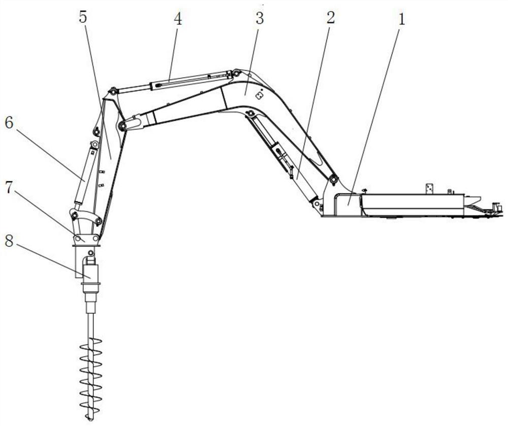
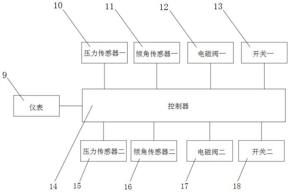
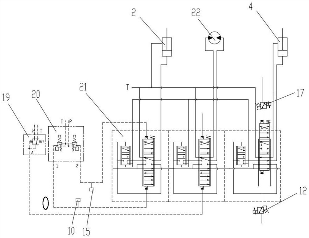
[0039] Such as figure 1 , figure 2 , image 3 and Figure 4 As shown, a hydraulic excavator auger rod implement control system includes a turntable 1, a boom cylinder 2, a boom 3, a stick cylinder 4, a stick 5, a bucket cylinder 6, a...


PUM


Abstract

The control system comprises a rotary table, a movable arm oil cylinder, a movable arm, a bucket rod oil cylinder, a bucket rod, a bucket oil cylinder, a spiral drill rod connecting mechanism and a spiral drill rod, and further comprises a controller, an instrument, a pressure sensor, a tilt angle sensor, an electromagnetic valve and a switch. The controller is electrically connected with the instrument, the pressure sensor, the tilt angle sensor, the electromagnetic valve and the switch. The electromagnetic valve is used for controlling the bucket rod linkage valve element to achieve inward retracting and outward swinging of the bucket rod. The tilt angle sensor is mounted on the movable arm and the bucket rod and used for identifying postures of the movable arm and the bucket rod; the switches comprise the first switch and the second switch, the first switch is used for triggering and recognizing the position of the spiral drill rod and triggering and recognizing the horizontal and vertical distance between a connecting shaft between the spiral drill rod and the bucket rod and a connecting shaft between the movable arm and the rotary table, and the second switch is used for triggering and starting the automatic control function of a spiral drill rod machine tool. According to the invention, inclination of a drilling pit is effectively avoided, perpendicularity of the drilling pit is ensured, operation difficulty is greatly reduced, and working efficiency is improved.

Description

technical field [0001] The invention relates to a control system and a control method of auger rod implements of a hydraulic excavator, belonging to the field of excavators. Background technique [0002] As an important construction machine, excavators are widely used in various earthwork operations. For micro excavators, auger rods are often used to drill holes for tree planting and bury utility poles. At present, the operation of rotary drilling rod equipment is firstly positioned at the position of the drilling pit, and by operating the pilot handle and foot valve, the movement of the boom, stick, and tool cylinder is realized to make the rotary drilling rod rotate, so the boom, bucket Coordinated operation of the rods to ensure that the auger rod moves as vertically as possible, which requires high operator skills, which may easily cause the drilling hole to tilt, and the verticality cannot be guaranteed. In addition, the depth of the drilling hole can only be identified...

Claims


Application Information

Patent Timeline
Patent Type & Authority Applications(China)
IPC IPC(8): E21B44/00
CPCE21B44/00
Inventor 郭会会于书敏张真畅马立国李效鹏
Owner XCMG EXCAVATOR MACHINERY
Why Eureka
Try Eureka