
PWM wave generation and duty cycle control method, device, timer and equipment

A control method and duty cycle technology, which is applied in pulse width modulation signal (PWM wave) wave generation and duty cycle control, timers and electronic equipment, and can solve the problems of increasing chip power consumption, low cost performance, and restricting development. , to achieve the effect of reducing computing requirements, less gate circuits, and improving control precision

Active Publication Date: 2022-06-17
ZHEJIANG GEOFORCECHIP TECH CO LTD
View PDF19 Cites 0 Cited by
  • Summary
  • Abstract
  • Description
  • Claims
  • Application Information

AI Technical Summary

Problems solved by technology

[0004] With the improvement of people's quality of life, on the one hand, a wide variety of wireless charging products have appeared on the market, and the market demand for DC conversion is also increasing; on the other hand, because high-precision duty cycle control often requires more expensive and more High-frequency MCU execution increases chip power consumption at the same time. In this way, existing DC power conversion products or technologies often have low cost performance and high power consumption, and more cost-sensitive products appear, and higher costs will Greatly limit the development of such products

Method used


Image

  • PWM wave generation and duty cycle control method, device, timer and equipment
  • PWM wave generation and duty cycle control method, device, timer and equipment
  • PWM wave generation and duty cycle control method, device, timer and equipment

Examples


Embodiment Construction

[0045] Exemplary embodiments of the present application will be described in more detail below with reference to the accompanying drawings. While exemplary embodiments of the present application are shown in the drawings, it should be understood that the present application may be embodied in various forms and should not be limited by the embodiments set forth herein. Rather, these embodiments are provided so that the application will be more thoroughly understood, and will fully convey the scope of the application to those skilled in the art.

[0046] It should be noted that, unless otherwise specified, the technical or scientific terms used in the present application should have the usual meanings understood by those skilled in the art to which the present application belongs.

[0047]The following describes a method, device, timer, and electronic device for generating a pulse width modulation signal wave and controlling a duty ratio according to the embodiments of the prese...


PUM


Abstract

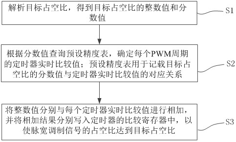
This application proposes a pulse width modulation signal wave generation and duty ratio control method, device, timer and electronic equipment. The pulse width modulation signal duty ratio control method is applied to a timer generating a pulse width modulation signal, including: Analyze the target duty cycle to obtain the integer value and fractional value of the target duty cycle; query the preset accuracy table according to the fractional value to determine the real-time comparison value of the timer for each PWM cycle; the preset accuracy table is used to record the target duty cycle The corresponding relationship between the fractional value of the timer and the real-time comparison value of the timer; add the integer value to the real-time comparison value of each timer, and write the addition results into the comparison register of the timer respectively, so that the pulse width modulation signal The duty cycle reaches the target duty cycle. This application does not require complex calculations, the program is relatively streamlined, and the demand for MCU resources is relatively low, and high-precision control of the duty cycle can be realized at low cost.

Description

technical field [0001] The present application belongs to the technical field of DC conversion, and in particular relates to a method, device, timer and electronic equipment for generating a pulse width modulated signal (PWM wave) wave and controlling a duty cycle. Background technique [0002] At present, in wireless charging related technologies, converting direct current to alternating current is an indispensable link for wireless power transmission. For example, the process of direct current conversion by wireless power transmitter is generally through MCU (Microcontroller Unit, micro control unit), control the output pulse width modulation wave (PWM wave), and control the bridge circuit composed of MOS tube to convert direct current into alternating current , and finally transmit the transmission through the coil. Among them, the size of the PWM duty cycle will directly affect the charging power. Therefore, most of the wireless power control at this stage adopts a met...

Claims


Application Information

Patent Timeline
Patent Type & Authority Patents(China)
IPC IPC(8): H03K7/08
CPCH03K7/08
Inventor 不公告发明人
Owner ZHEJIANG GEOFORCECHIP TECH CO LTD
Learn More