Supercharge Your Innovation With Domain-Expert AI Agents!

Motor rotor production and processing equipment and production and processing method thereof

A technology for processing equipment and motor rotors, applied in metal processing equipment, grinding/polishing equipment, manufacturing stator/rotor bodies, etc., can solve problems such as reduced work efficiency, inflexible use, inconvenience, etc. Good grinding effect and convenient clamping effect

Active Publication Date: 2022-03-25
安徽智鸥驱动科技有限公司
View PDF6 Cites 0 Cited by
  • Summary
  • Abstract
  • Description
  • Claims
  • Application Information

AI Technical Summary

Problems solved by technology

[0010]In the process of motor production, it is often necessary to use rotor processing equipment to grind the rotor. However, the existing rotor production and processing equipment needs to be manually clamped during use. Finally, it is necessary to manually remove and reinstall other rotors to be polished. The manual operation is cumbersome, inflexible, inconvenient, time-consuming and laborious, and reduces work efficiency. Therefore, we propose a motor rotor production and processing equipment and its production and processing method

Method used


Image

  • Motor rotor production and processing equipment and production and processing method thereof
  • Motor rotor production and processing equipment and production and processing method thereof
  • Motor rotor production and processing equipment and production and processing method thereof

Examples


Embodiment 1

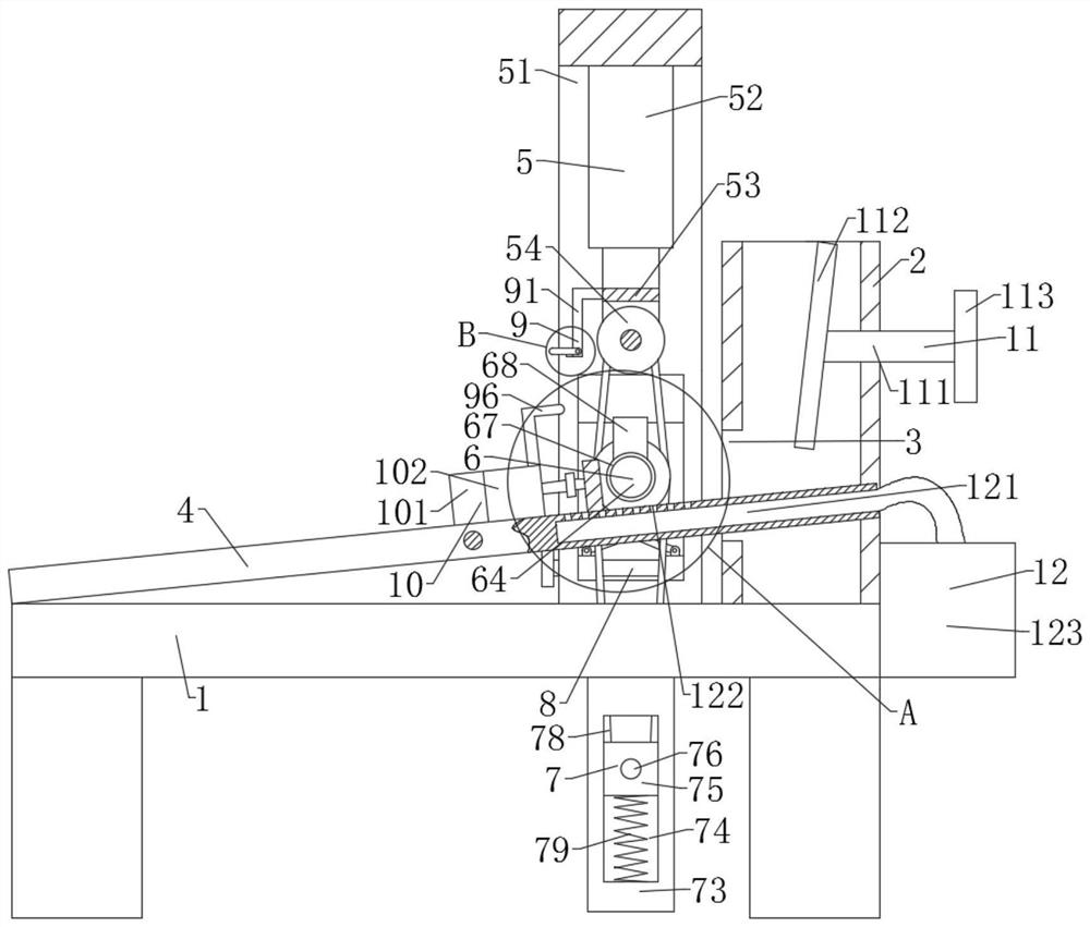
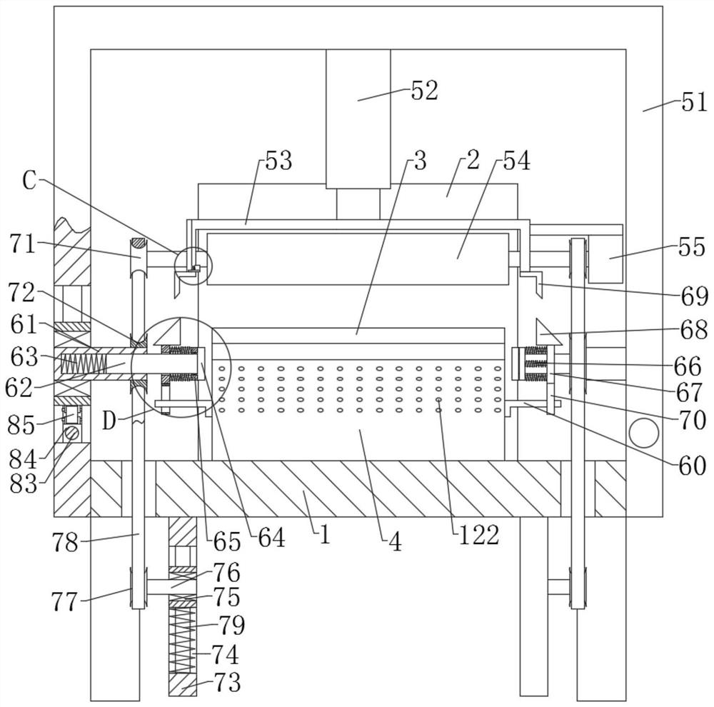
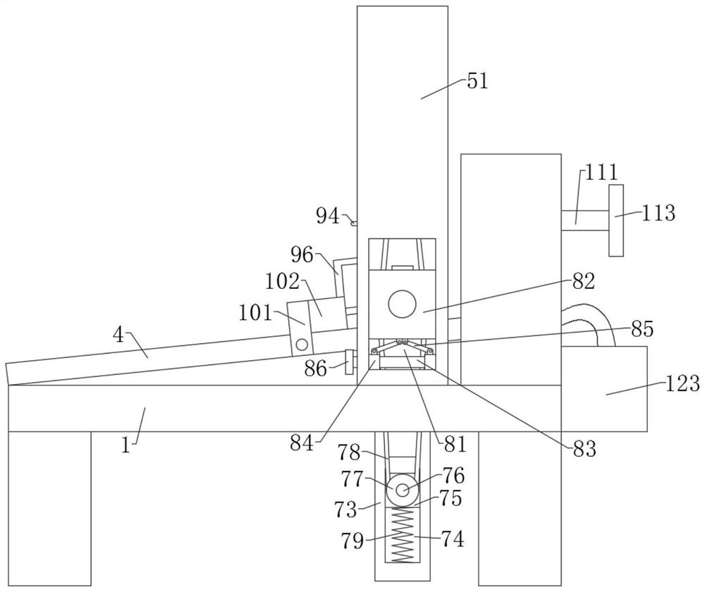
[0044] combine Figure 1-8 , the present invention provides a technical solution, a motor rotor production and processing equipment, including a base 1, the base 1 is fixedly connected with a discharge box 2, the left side wall of the discharge box 2 is provided with a discharge port 3; the top of the base 1 is provided with The inclined blanking plate 4, the right end of the blanking plate 4 passes through the discharge port 3 and is fixedly connected with the inner wall of the discharge box 2; the top of the base 1 and the left side of the discharge box 2 are provided with a processing component 5, and the processing component 5 is set There are a clamping component 6, a driving component 7, a lifting component 8, and a linkage component 9. The clamping component 6 cooperates with the driving component 7 and the lifting component 8; the top of the base 1 is provided with a baffle component 10, the baffle component 10 and the linkage component 9 Cooperate.

[0045] Wherein, ...

Embodiment 2

[0056] combine figure 1 In order to prevent the rotor from being violently hit or knocked during the falling process in the discharge box 2, a motor rotor production and processing equipment also includes an adjustment assembly 11, the adjustment assembly 11 includes a third screw 111, and the third screw 111 is screwed on the discharge box 2. On the right side wall of the material box 2, the left end of the third screw rod 111 stretches into the inner cavity of the material box 2 and is rotatably connected with an inclined deflector 112, and the right end is fixedly connected with a handle 113.

[0057] A specific application of this embodiment is:

[0058] The rotor rolls down along the left side wall of the inclined deflector 112, which can prevent the rotor from being violently hit or knocked during the falling process. The left side wall of the deflector 112 and the inner cavity of the discharge box 2 can be adjusted by the third screw 111. The distance between the side ...

Embodiment 3

[0060] combine figure 1 , 5 , in order to keep the working environment neat and clean, and to ensure the health of the staff, a motor rotor production and processing equipment also includes a dust removal assembly 12, the dust removal assembly 12 includes a dust suction chamber 121, and the dust suction chamber 121 is located inside the blanking plate 4 And located below the processing unit 5 , the top of the dust suction cavity 121 is provided with a number of suction holes 122 ;

[0061] A specific application of this embodiment is:

[0062] When the grinding roller 54 grinds the rotor, the dust suction end of the vacuum cleaner 123 sucks the dust or debris generated by the grinding through the dust suction chamber 121 and the dust suction hole 122, which ensures the cleanliness and cleanliness of the working environment and the safety of the staff. Healthy body.

[0063] The electrical components used in this patent are all commercially available, and their specific stru...


PUM


Abstract

According to the motor rotor producing and machining equipment and the producing and machining method thereof, the adjusting assembly is arranged, so that a rotor can roll down along the flow guide plate, and the rotor is prevented from being strongly impacted; the baffle assembly is arranged, so that the rotor can be blocked under the grinding roller; the output end of the motor drives the grinding roller, the driving assembly and the clamping assembly to rotate. When the mounting frame and the grinding roller move downwards, the clamping assembly clamps the rotor, then the grinding roller grinds the rotating rotor, and the dust removal assembly sucks dust generated by grinding; and after grinding is finished, the mounting frame moves upwards to drive the linkage rod to move upwards, the linkage rod drives the driving rod and the baffle assembly to rotate, then the machined rotor penetrates through the lower portion of the baffle along the discharging plate and rolls to the left side of the discharging plate, finally, the linkage rod is away from the driving rod, and the baffle falls back to the top of the discharging plate under the action of gravity.

Description

technical field [0001] The invention relates to the technical field of motor rotor processing equipment, more specifically, it relates to a motor rotor production and processing equipment and a production and processing method thereof. Background technique [0002] A motor, commonly known as a motor, refers to an electromagnetic device that converts or transmits electrical energy according to the law of electromagnetic induction. The motor is represented by the letter M in the circuit, and the old standard is represented by D. Its main function is to generate driving torque as a power source for electrical appliances or various machines. The generator is represented by the letter G in the circuit. Its main function is Convert mechanical energy into electrical energy. [0003] According to the type of working power supply: it can be divided into DC motor and AC motor; DC motor can be divided according to the structure and working principle: brushless DC motor and brushed DC ...

Claims


Application Information

Patent Timeline
IPC IPC(8): B24B19/00B24B41/00B24B41/02B24B47/14B24B47/12B24B41/04B24B41/06B24B55/06B24B1/00H02K15/02
CPCB24B19/00B24B41/005B24B41/02B24B47/14B24B47/12B24B41/04B24B41/062B24B55/06B24B1/00H02K15/02
Inventor 陈凡崔德新张志峰
Owner 安徽智鸥驱动科技有限公司
Features
  • R&D
  • Intellectual Property
  • Life Sciences
  • Materials
  • Tech Scout
  • Unparalleled Data Quality
  • Higher Quality Content
  • 60% Fewer Hallucinations
Learn More