Large intelligent automatic water pouring machine
A water pouring machine, intelligent technology, applied in the direction of stove type, cleaning method and utensils, furnace, etc., can solve the problems of inability to drain water in pipes, reduce manual operation time, increase production efficiency, etc., to improve the effect of pouring water, solve The problem of water accumulation in the pipeline and the effect of fixing it firmly
- Summary
- Abstract
- Description
- Claims
- Application Information
AI Technical Summary
Problems solved by technology
Method used
Image
Examples
Embodiment 1
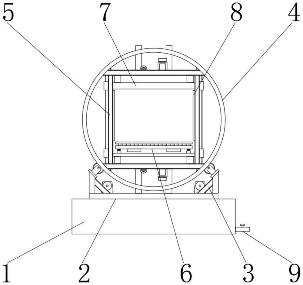
[0020] Such as figure 1 As shown, the large-scale intelligent automatic pouring machine, the large-scale intelligent automatic pouring machine includes a pool 1, the upper outer surface of the pool 1 is provided with a frame base 2, and the upper outer surface of the rack base 2 is provided with a driving device 3, the driving device The outer surface of the upper end of 3 is provided with a ring frame 4, the middle part of the ring frame 4 is provided with a square frame 5, the middle part of the square frame 5 is provided with a shaking water mechanism 6, the upper end outer surface of the square frame 5 is provided with an upper pneumatic pressure plate 7, and the square frame The outer surface of both sides of 5 is provided with side pneumatic splint 8, and the outer surface of one side of pool 1 is provided with drain valve pipe 9.
Embodiment 2
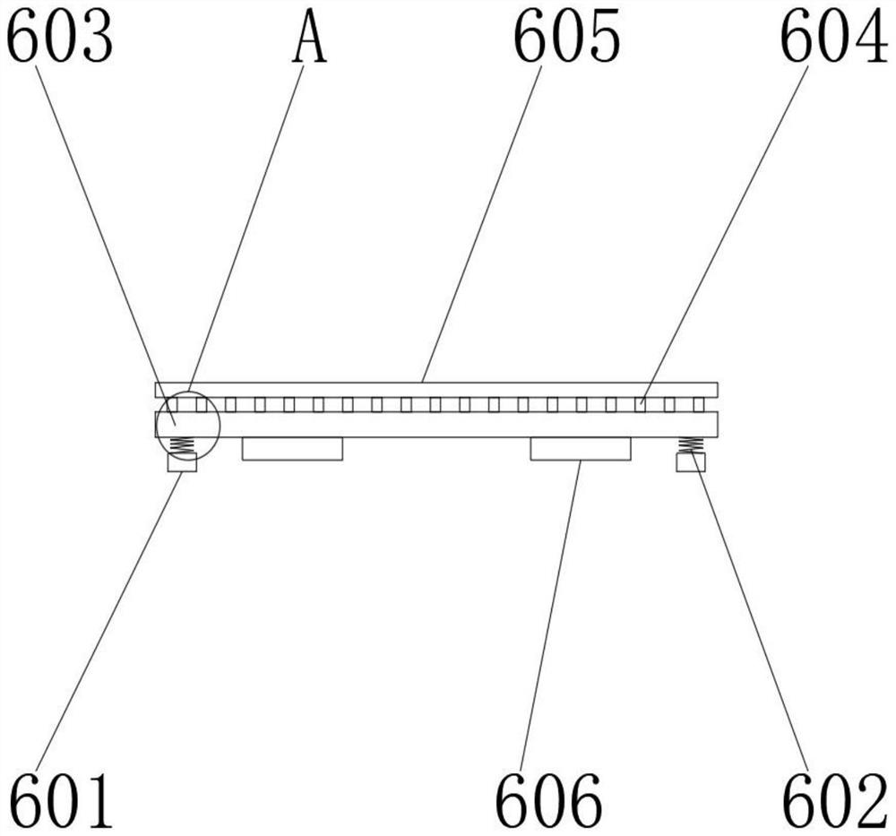
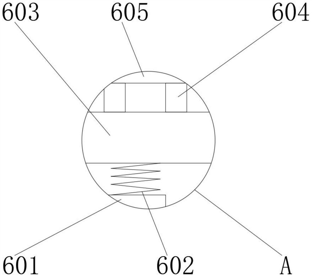
[0022] Such as figure 2 As shown, the shaker mechanism 6 includes a connection block 601, a spring 602, a base plate 603, a rubber column 604, a placement plate 605, and a vibrating motor 606. , the rubber column 604 is located on the upper outer surface of the base plate 603, the placement plate 605 is located on the outer surface of one end of the rubber column 604, the vibration motor 606 is located on the lower outer surface of the base plate 603, and the outer surface of one end of the connection block 601 is connected to the outer surface of the other end of the spring 602. Detachable connection, the outer surface of one end of the spring 602 is detachably connected with the outer surface of the lower end of the base plate 603, the outer surface of the upper end of the base plate 603 is detachably connected with the outer surface of the other end of the rubber column 604, and the rubber column 604 and the placement plate 605 are integrally formed structure, the outer su...
Embodiment 3
[0024] Such as figure 1 As shown, the outer surface of the upper end of the pool 1 is detachably connected to the outer surface of the lower end of the frame base 2, the outer surface of one side of the pool 1 is detachably connected to the outer surface of one end of the drain valve pipe 9, and the outer surface of the upper end of the frame base 2 It is detachably connected with the outer surface of the lower end of the driving device 3, the outer surface of the upper end of the driving device 3 is flexibly connected with the outer wall of the ring frame 4, the inner wall of the ring frame 4 is detachably connected with the outer surfaces of both ends of the square frame 5, and the outer surface of the square frame 5 The outer surfaces of both sides are detachably connected to the outer surface of one end of the side pneumatic splint 8. The driving device 3 includes a servo motor, a roller and a transmission belt. 4 Hover at 90 degrees, 180 degrees and 270 degrees, which can...
PUM
 Abstract
Description
Claims
Application Information
 - R&D
- Intellectual Property
- Life Sciences
- Materials
- Tech Scout
- Unparalleled Data Quality
- Higher Quality Content
- 60% Fewer Hallucinations
Browse by: Latest US Patents, China's latest patents, Technical Efficacy Thesaurus, Application Domain, Technology Topic, Popular Technical Reports.
© 2025 PatSnap. All rights reserved.Legal|Privacy policy|Modern Slavery Act Transparency Statement|Sitemap|About US| Contact US: help@patsnap.com


