
Manufacturing and mounting method for combined wall of fabricated house

An installation method and a combined technology are applied in the field of production and installation of combined walls, which can solve the problems of restricting the production of light steel keel and lightweight concrete combined houses, poor thermal insulation, fire prevention and sound insulation performance, and difficult to control installation accuracy, and achieve It is not easy to overall and local instability, good fire and sound insulation performance, and easy to control the installation accuracy.

Pending Publication Date: 2022-03-25
洛阳北玻轻晶石新材料有限公司
View PDF9 Cites 1 Cited by
  • Summary
  • Abstract
  • Description
  • Claims
  • Application Information

AI Technical Summary

Problems solved by technology

[0002] Lightweight steel structure prefabricated houses have the advantages of light weight, good seismic performance, short construction period, energy saving and environmental protection, and high degree of industrialization. Its shortcomings seriously affect its promotion and application
The combined walls of existing prefabricated houses are usually prefabricated in the factory or on site, so wet work of pouring concrete is required on site, the installation accuracy is not easy to control, and the combined walls are prone to overall and local instability and corrosion. Thermal insulation, fire prevention and sound insulation are poor, and the cost of construction and installation is high, which limits the production of large quantities of light steel keel lightweight concrete composite houses

Method used


Image

  • Manufacturing and mounting method for combined wall of fabricated house
  • Manufacturing and mounting method for combined wall of fabricated house
  • Manufacturing and mounting method for combined wall of fabricated house

Examples


specific Embodiment approach

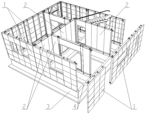
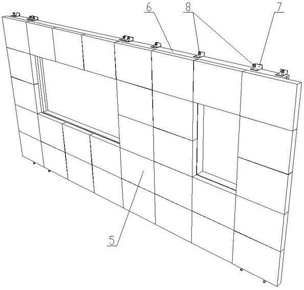
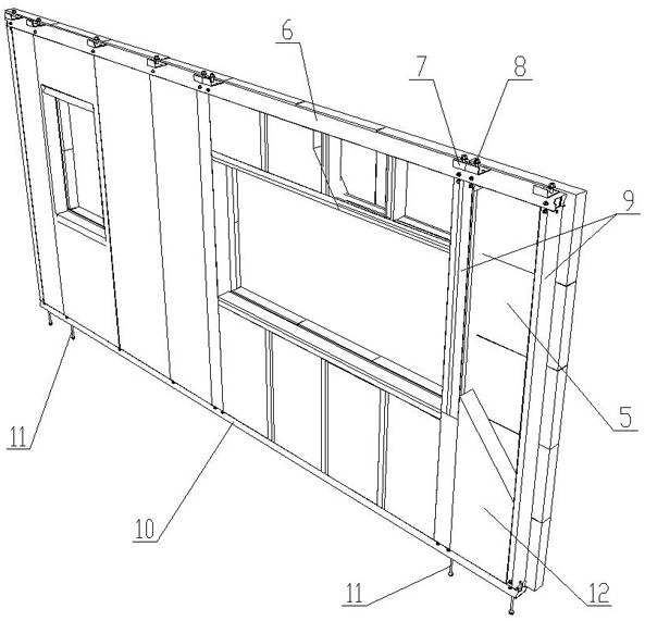
[0018] Referring to the accompanying drawings, the specific implementation is as follows:

[0019] A method for manufacturing and installing a combined wall for a prefabricated house, comprising the following steps:

[0020] Install a plurality of vertical keels 9 between the sky keel 6 and the ground keel 10 respectively, process connection grooves on the surface of the light microcrystalline stone plate 5, and then install the light microcrystalline stone plate 5 on the multiple vertical keels 9 One side of the connecting groove is aligned with multiple vertical keels 9 respectively, and then filled with lightweight concrete 12 between the multiple vertical keels 9, and the lightweight concrete 12 is bonded with the lightweight microcrystalline stone slab 5 , forming a concrete wall layer located inside the outer wall 1 .

[0021] A plurality of vertical keels 9 are respectively installed between the sky keel 6 and the ground keel 10, then a plurality of keel braces 13 are ...


PUM


Abstract

A manufacturing and mounting method of a combined wall for a fabricated house comprises the steps that firstly, a plurality of outer walls and inner walls are prefabricated, each outer wall is provided with a light microcrystalline plate and a concrete wall layer, each inner wall is provided with a concrete wall layer, and a plurality of floor connecting pieces are arranged on the top sides of ceiling keels of the outer walls and the inner walls in a penetrating mode through a plurality of connecting bolts; a plurality of foundation bolts are arranged on the bottom sides of the ground keels of the outer wall body and the inner wall body in a penetrating mode; a concrete foundation is manufactured, a plurality of wall body mounting holes are machined in the concrete foundation, then the wall body mounting holes are filled with grouting materials, the outer wall body and the inner wall body are hoisted to the concrete foundation, and the foundation bolts are inserted into the wall body mounting holes respectively; and the floor slab is hoisted to the top side of the bottommost layer of combined wall body, and the outer wall body and the inner wall body are hoisted to the lower layer of combined wall body layer by layer. The combined wall can be prefabricated in a factory or on site, wet operation of concrete pouring on site is avoided, and the installation precision is easy to control.

Description

technical field [0001] The invention relates to the field of prefabricated houses, in particular to a method for manufacturing and installing a combined wall used in a prefabricated house. Background technique [0002] Lightweight steel structure prefabricated houses have the advantages of light weight, good seismic performance, short construction period, energy saving and environmental protection, and high degree of industrialization. Its shortcomings seriously affect its promotion and application. The combined walls of existing prefabricated houses are usually prefabricated in the factory or on site, so wet work of pouring concrete is required on site, the installation accuracy is not easy to control, and the combined walls are prone to overall and local instability and corrosion. The thermal insulation, fire prevention and sound insulation performance are poor, and the cost and installation cost are high, which limits the production of large quantities of light steel kee...

Claims


Application Information

Patent Timeline
Patent Type & Authority Applications(China)
IPC IPC(8): E04B1/343E04B1/38E04B2/56E04B2/58E02D27/00E04B5/02E04B1/41E04G21/14E04G21/02B28B1/14B28B23/02
CPCE04B1/34315E04B1/34384E04B1/38E04B2/562E04B2/58E02D27/00E04B5/02E04B5/023E04B1/41E04G21/14E04G21/02B28B1/14B28B23/02
Inventor 刘桂林赵欢旗郑智慧
Owner 洛阳北玻轻晶石新材料有限公司
Learn More