

Gas sensor and manufacturing method thereof
A technology of gas sensor and manufacturing method, which is applied in the direction of instruments, scientific instruments, measuring devices, etc., and can solve the problems that the gas-sensing layer is easy to fall off, the bonding force between the gas-sensing layer and the ceramic substrate is uneven, and the coating of the gas-sensing material cannot be guaranteed. , to achieve the effect of not easy to disappear and stable gas sensitivity
- Summary
- Abstract
- Description
- Claims
- Application Information
AI Technical Summary
Problems solved by technology
Method used
Image

Examples
Embodiment 1
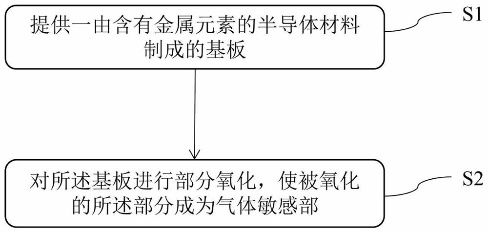
[0030] This embodiment provides a method for manufacturing a gas sensor, such as figure 1 As shown, the preparation method includes:
[0031] Step S1, providing a substrate 1 made of a semiconductor material containing metal elements. Preferably, the substrate 1 is made of AlGaInN material.
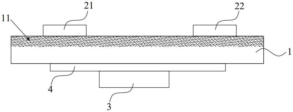
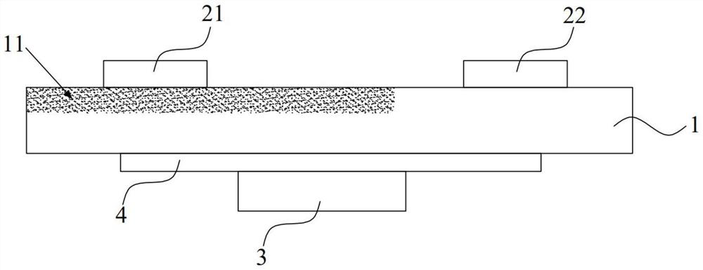
[0032] Step S2 , partially oxidize the substrate 1 , and make the oxidized portion become the gas sensitive part 11 . Specifically, the method for oxidizing part of the substrate 1 may adopt a strong oxidant reaction process or an ultraviolet assisted oxidation process. Wherein, the specific scope of said part can be determined according to the actual situation, for example: as Figure 2a As shown, the part can occupy the entire area of a certain side of the substrate 1, or as Figure 2b As shown, the part may occupy a partial area of a certain surface of the substrate 1 .
[0033] The substrate 1 and the gas sensitive part 11 of the gas sensor manufactured by the manufacturing m...
Embodiment 2
[0040] Different from Embodiment 1, in the manufacturing method of this embodiment, before oxidizing the portion, the manufacturing method further includes: performing surface treatment on the portion of the substrate 1 to be oxidized, so that the The step of microstructuring the surface of the portion of the substrate to be oxidized. Wherein, the specific shape of the microstructure can be determined according to actual needs. Preferably, the microstructure may be a columnar structure arranged in an array or a blind hole structure.
[0041] In this embodiment, after the above steps, the gas sensitive part 11 formed by subsequent oxidation will have the above microstructure, and the microstructure can increase the surface area of the gas sensitive part 11, thereby increasing the gas sensitive part 11. The contact area with the detection gas can improve the sensitivity of the gas sensor.
Embodiment 3
[0043] Different from Embodiment 1, in the manufacturing method of this embodiment, after the formation of the first electrode 21 and the second electrode 22, it is also included on the substrate 1 other than the gas sensitive part 11 Steps for setting up heating unit 3.
[0044]Specifically, an adhesive layer 4 is formed on the substrate 1 other than the gas sensitive part 11 , and the heating unit 3 is disposed on the adhesive layer 4 after the adhesive layer 4 is formed. The heating unit 3 is used to adjust the temperature of the substrate 1 and the gas sensitive part 11, so that the temperature of the gas sensitive part 11 is close to the temperature of the surrounding gas to be measured, thereby further improving the temperature of the gas sensor. detection sensitivity.
PUM
 Abstract
Description
Claims
Application Information